
Implementation method of cement soil mixing stirring drilling machine

A technology of mixing and stirring, cement and soil, applied in drilling equipment and methods, earth-moving drilling, drilling equipment, etc.

Inactive Publication Date: 2016-11-02
刘玉秋
View PDF0 Cites 0 Cited by
  • Summary
  • Abstract
  • Description
  • Claims
  • Application Information

AI Technical Summary

Problems solved by technology

[0002] At present, cement-soil mixing drilling rigs can only take rectangular cement-soil piles

Method used


Image

  • Implementation method of cement soil mixing stirring drilling machine
  • Implementation method of cement soil mixing stirring drilling machine
  • Implementation method of cement soil mixing stirring drilling machine

Examples


Embodiment Construction

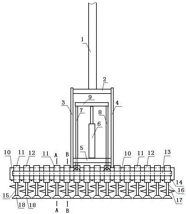
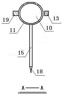
[0015] Accompanying drawing is a kind of concrete embodiment of the present invention, and the lower end of riser pipe 1 of this embodiment is fixed with the first transverse arm 2, and the upper end of the first vertical arm 3 is fixed at the left end of the first transverse arm, and the second arm is fixed at the right end of the first transverse arm. The upper end of the vertical arm 4, the lower end of the first vertical arm is fixed on the horizontal tube 10, the lower end of the second vertical arm is also fixed on the horizontal tube, and the horizontal tube is covered with a plurality of first overcoats 11, and every two adjacent Between the first overcoat, a second overcoat 12 is set on the cross tube, and a plurality of first overcoats are fixed by the fifth cross arm 19 of the rear side, and a plurality of second overcoats are fixed by the fourth cross arm 13 of the front side; The left end of cross arm 5 is fixed on the bottom of the first vertical arm, the right en...


PUM


Abstract

The invention provides an implementation method of a cement soil mixing stirring drilling machine. When the cement soil mixing stirring drilling machine works, a jack stretches out and draws back in a reciprocating mode to push and pull a fifth transverse arm through a third vertical arm in a reciprocating mode and push and pull a fourth transverse arm through a fourth vertical arm in a reciprocating mode, and thus a plurality of first knife arms as well as triangular knives on the first knife arms and trapezoid knives at the lower ends of the first knife arms are driven to swing front and back in a reciprocating mode with a transverse pipe being the axis; at the same time, a plurality of second knife arms as well as triangular knives on the second knife arms and trapezoid knives at the lower ends of the second knife arms are driven to swing back and front in a reciprocating mode with the transverse pipe being the axis; and meanwhile, high-pressure water enters a vertical pipe, enters the transverse pipe through a water pipe and is sprayed out through a plurality of nozzles on the lower part of the transverse pipe, the trapezoid knives at the lower ends of the first knife arms and the trapezoid knives at the lower ends of the second knife arms cut soil during relative swing, the triangular knives on the first knife arms and the triangular knives on the second knife arms stir the soil with water to form slurry during relative swing, the slurry flows out of rectangular holes, the downward drilling power is provided by the vertical pipe, and the rectangular holes are formed in the downward drilling process of the drilling machine.

Description

technical field [0001] The invention relates to a drilling rig, in particular to an implementation method of a cement-soil mixing drilling rig used in foundation engineering. Background technique [0002] At present, the cement-soil mixing and stirring drilling rig can only take rectangular cement-soil piles. Contents of the invention [0003] The present invention makes up for the above shortcomings, and provides an implementation method of a cement-soil mixing drilling rig. [0004] The present invention is achieved through the following technical solutions: [0005] A cement-soil mixing drilling rig, the lower end of the standpipe is fixed with a first cross arm, the left end of the first cross arm is fixed with the upper end of the first vertical arm, the right end of the first cross arm is fixed with the upper end of the second vertical arm, the upper end of the first vertical arm is The lower end is fixed on the horizontal tube, and the lower end of the second vert...

Claims


Application Information

Patent Timeline
IPC IPC(8): E02D5/46E21B4/16E21B7/00
CPCE02D5/46E21B4/16E21B7/00
Inventor 刘玉秋
Owner 刘玉秋
Learn More