Diaphragm Valve

A technology of diaphragm valves and diaphragms, applied in the direction of diaphragm valves, diaphragms, valve details, etc., can solve problems such as large friction, difficulty, and limit the lateral size of the valve driver, and achieve the effect of small torque

Active Publication Date: 2016-11-02
BURKERT WERKE
View PDF9 Cites 4 Cited by
  • Summary
  • Abstract
  • Description
  • Claims
  • Application Information

AI Technical Summary

Problems solved by technology

In addition, due to the size of the thread and the contact surface between the union nut and the housing of the valve drive, high frictional forces result
Due to this high resistance, it is relatively difficult to achieve just the desired optimum axial clamping force for the diaphragm dur

Method used


Image

  • Diaphragm Valve
  • Diaphragm Valve
  • Diaphragm Valve

Examples


Embodiment Construction

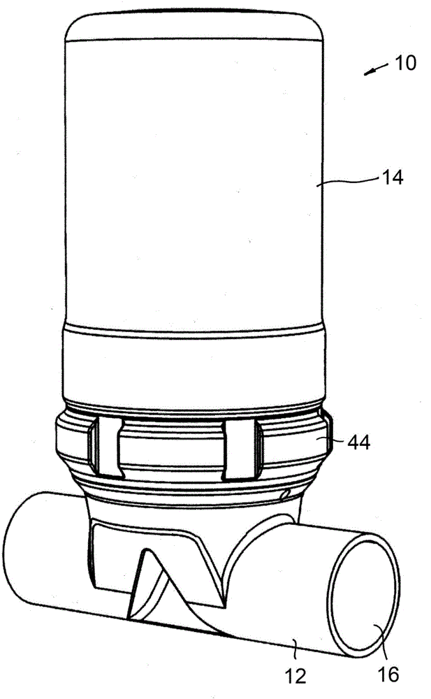
[0037] exist figure 1 A diaphragm valve 10 is shown in , which has a valve body 12 , here in the form of a tube, and a valve drive 14 fastened to the valve body 12 .

[0038] In this embodiment, the valve body is tubular as described and has a flow channel inside it, in which the figure 1 Exit 16 can be seen in . The flow passage can be selectively interrupted or opened in the valve body 12 by the valve driver 14, thereby closing or opening the valve.

[0039] Preferably, this should not be construed as limiting, the valve body 12 may be a one-piece part, deformed or manufactured by casting. Metal or plastic can be used as material.

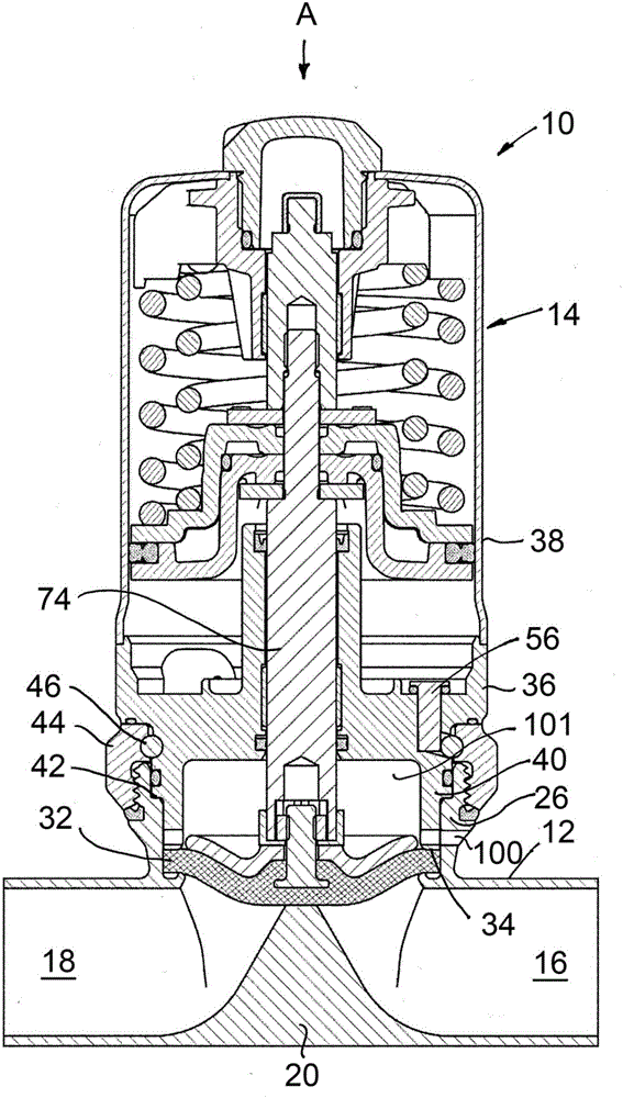
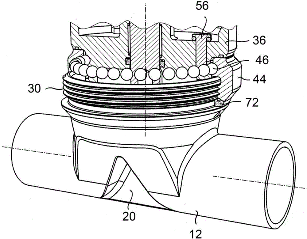
[0040] exist figure 2 In addition to the outlet 16, the inlet 18 of the flow channel can also be seen. A spacer tab 20 extends laterally into the flow channel between the inlet 18 and the outlet 16 and divides the flow channel into two sections. The upper side 22 of the spacer tab (Absperrsteg) 20 (see Figure 6 ) outwards to the pipe axi...


PUM


Abstract

A diaphragm valve has a valve body which includes at least one flow passage for fluid flow, a valve drive including a housing, and a diaphragm which can be deflected by the valve drive, in order to selectively open and close the flow passage. The rim of the diaphragm is axially clamped in a fluid-tight way between valve body and valve drive, wherein clamping of the diaphragm is effected by a screw-nut connection and the screw and the nut surround the rim of the diaphragm as seen in actuating direction of the valve drive and one of the two parts formed by screw and nut is non-rotatably provided at the valve body or at the valve drive. The other one of the two parts can be screwed in or on and additionally is rotatorily movable. The movable part is supported on the valve drive or on the valve body by an anti-friction bearing.

Description

technical field [0001] The invention relates to a diaphragm valve having: a valve body having at least one flow channel for fluid communication; a valve drive having a housing; and a diaphragm which can be deflected by the valve drive so that selectively opening and closing the flow channel, wherein the diaphragm is axially clamped between the valve body and the valve driver in a fluid-tight manner on the edge side, and the diaphragm is clamped by means of a screw-nut connection, wherein the Viewed in the actuating direction of the valve drive, the screw and nut surround the diaphragm on the peripheral side, and one of the two parts formed by the screw and nut is arranged non-rotatably on the valve body or on the valve drive, and where the two The other of the parts can be screwed in and moved rotationally. Background technique [0002] A diaphragm valve of this type is known from DE 101 53 362 B4. Here, the housing of the valve drive is fastened to the valve body by means...

Claims


Application Information

Patent Timeline
IPC IPC(8): F16K7/12
CPCF16K7/126F16K17/196F16K27/0236F16K27/0281F16K51/00
Inventor 维尔纳·尤里克拉尔夫·凯特曼
Owner BURKERT WERKE
Why Eureka
Try Eureka