Coin counting device and conveying mechanism thereof

A technology of conveying mechanism and counting device, which is applied in the direction of coin counting, handling coins or valuable banknotes, instruments, etc., which can solve the problems of easy congestion of coins, and achieve the effect of easy handling and easy congestion

Inactive Publication Date: 2016-11-02
HENAN UNIV OF SCI & TECH
View PDF16 Cites 2 Cited by
  • Summary
  • Abstract
  • Description
  • Claims
  • Application Information

AI Technical Summary

Problems solved by technology

[0003] The purpose of the present invention is to provide a conveying mechanism, which aims to solve the problem that coins are easily blocked when conveying to the inlet of the collecting pipe in the prior art

Method used


Image

  • Coin counting device and conveying mechanism thereof
  • Coin counting device and conveying mechanism thereof
  • Coin counting device and conveying mechanism thereof

Examples


Embodiment Construction

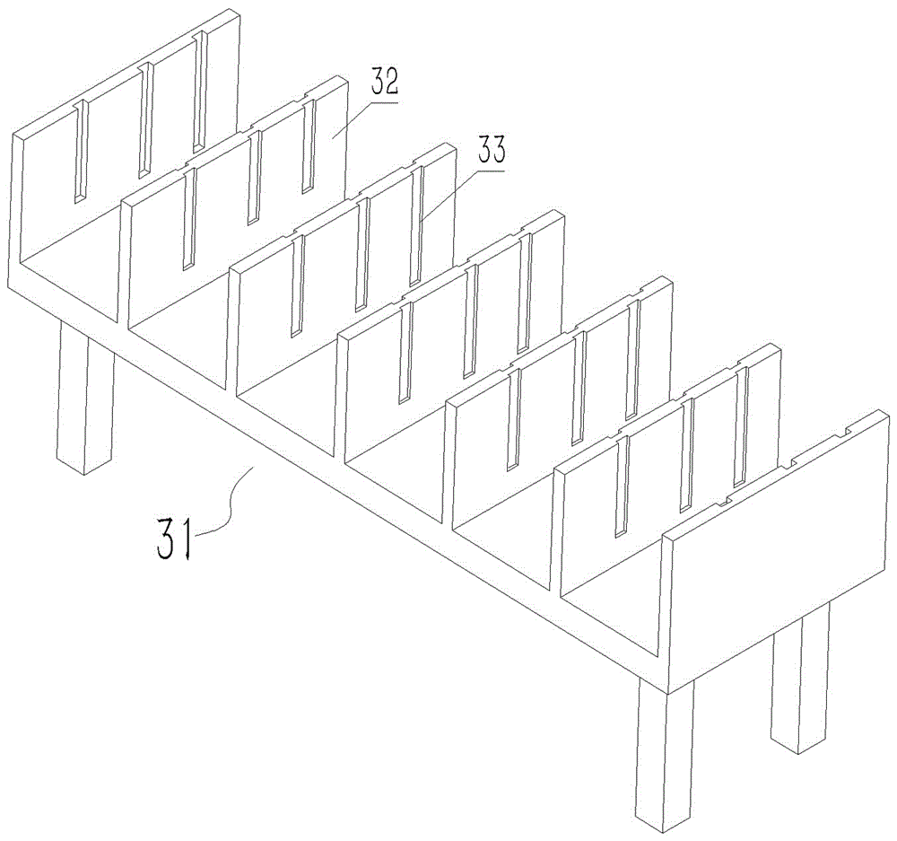
[0029] The embodiment of coin counting device among the present invention: as Figure 1 to Figure 12 As shown, the device includes a machine base 1 and a conveying mechanism 2, a separation mechanism 3, and a collection mechanism 4 arranged on it. The conveying mechanism 2 pushes the coins into the separation mechanism 3. After the separation mechanism 3 divides the coins, the coins are One by one, the coins are sent into the collection mechanism 4, and the coins fall by their own weight in the collection mechanism 4 to complete counting and collection.

[0030] The conveying mechanism 2 includes a coin pool 21 fixed on the machine base 1. The coin pool 21 extends along the front-to-back direction, and the top and the front and rear sides of the coin pool 21 are open, especially the rear opening is a pushing port for coins. The front side of the coin pool 21 is provided with a drive motor 22, the drive motor 22 is fixed on the motor base 23 flush with the support 1, and the ou...


PUM


Abstract

The invention discloses a coin counting device and a conveying mechanism thereof. The conveying mechanism comprises a coin pool which is used for accommodating coins and a push plate which is used for pushing out the coins. A power device is connected on the push plate in a transmission way. A controller controlling action of the power device is connected on the power device. A range finding sensor and/or a displacement sensor and/or a speed sensor are/is connected on the controller. When the coins are congested and then the push plate stops moving, the sensor can control the power device to stop or reversely output through the controller so as to react before congestion of the coins and process the congested coins, and the problem in the prior art that the coins are liable to be congested when the coins are conveyed to a collection pipe can be solved and thus the conveying mechanism has the advantages of reacting in congestion of the coins and processing congestion.

Description

technical field [0001] The invention relates to a coin counting device and its conveying mechanism. Background technique [0002] At present, bus companies, banks and other units often receive a large number of coins. At present, most of the coin processing methods remain in manual counting by staff. During the counting process, the workload is heavy and cumbersome. Only some conveying mechanisms in the prior art are mostly: 1, utilize centrifugal force, disclose a kind of coin separator and coin separation method as Chinese patent document CN100504934C, comprise centrifugal separation device and the collection pipe that coin delivery mouth is connected The inner wall of the collection tube is provided with a counting sensor, so that under the centrifugal force of the separation device, the coins enter the collection tube and fall by their own weight. During the falling process, the coins trigger the counting sensor to count, so as to realize the rapid processing of the coin...

Claims


Application Information

Patent Timeline
Patent Type & Authority Applications(China)
IPC IPC(8): G07D9/00
CPCG07D9/008
Inventor 邱兆美张海峰周伟光马延武张伏王俊毛鹏军
Owner HENAN UNIV OF SCI & TECH
Why Eureka
Try Eureka