A kind of antenna and mobile terminal
An antenna and antenna radiation technology, applied in the direction of the antenna, antenna components, antenna grounding switch structure connection, etc., can solve the problems of poor antenna effect, the antenna cannot change the initial impedance position of the antenna, etc., to improve the performance of the antenna and achieve good matching and tuning. Effect
- Summary
- Abstract
- Description
- Claims
- Application Information
AI Technical Summary
Problems solved by technology
Method used
Image
Examples
no. 1 example
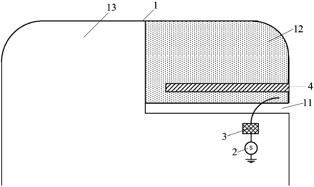
[0019] see figure 1 As shown, the embodiment of the present invention provides an antenna, which includes a metal back cover 1 , an antenna feed-in terminal 2 , a main matching circuit 3 and an antenna resonant plate 4 .
[0020] Wherein, the metal back cover 1 is provided with a slit 11, and the slit 11 divides the metal back cover 1 into an antenna radiation arm 12 and a reference ground 13, one end of the antenna feeding end 2 is grounded, and the antenna The other end of the feeding end 2 is connected to one end of the main matching circuit 3, the other end of the main matching circuit 3 is connected to the antenna radiation arm 12, and one end of the antenna resonating plate 4 is connected to the antenna radiation arm 12, and the other end of the antenna resonating plate 4 is suspended.
[0021] It should be noted that the metal back cover 1 is arranged on the back of the mobile terminal, and the metal back cover 1 can also extend to the side of the mobile terminal to fo...
no. 2 example
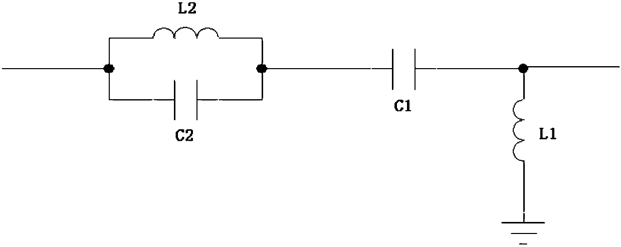
[0039] see figure 1 with image 3 As shown, the embodiment of the present invention also provides an antenna, including a metal back cover 1 , an antenna feed-in terminal 2 , a main matching circuit 3 and an antenna resonant plate 4 .
[0040] Wherein, the metal back cover 1 is provided with a slit 11, the slit 11 divides the metal back cover 1 into an antenna radiation arm 12 and a reference ground 13, one end of the antenna feeding end 2 is grounded, and the antenna The other end of the feeding end 2 is connected to one end of the main matching circuit 3, the other end of the main matching circuit 3 is connected to the antenna radiation arm 12, and one end of the antenna resonating plate 4 is connected to the antenna radiation arm 12, and the other end of the antenna resonating plate 4 is suspended.
[0041]It should be noted that the antenna resonating plate 4 may be a metal plate for antenna radiation. Usually, the extension direction of the antenna resonator plate 4 is...
no. 3 example
[0054] see figure 1 with Figure 4 As shown, the embodiment of the present invention also provides an antenna, including a metal back cover 1 , an antenna feed-in terminal 2 , a main matching circuit 3 and an antenna resonant plate 4 .
[0055] Wherein, the metal back cover 1 is provided with a slit 11, and the slit 11 divides the metal back cover 1 into an antenna radiation arm 12 and a reference ground 13, one end of the antenna feeding end 2 is grounded, and the antenna The other end of the feeding end 2 is connected to one end of the main matching circuit 3, the other end of the main matching circuit 3 is connected to the antenna radiation arm 12, and one end of the antenna resonating plate 4 is connected to the antenna radiation arm 12, and the other end of the antenna resonating plate 4 is suspended.
[0056] It should be noted that the antenna resonating plate 4 may be a metal plate for antenna radiation. Usually, the extension direction of the antenna resonator plat...
PUM
 Abstract
Description
Claims
Application Information
 - R&D
- Intellectual Property
- Life Sciences
- Materials
- Tech Scout
- Unparalleled Data Quality
- Higher Quality Content
- 60% Fewer Hallucinations
Browse by: Latest US Patents, China's latest patents, Technical Efficacy Thesaurus, Application Domain, Technology Topic, Popular Technical Reports.
© 2025 PatSnap. All rights reserved.Legal|Privacy policy|Modern Slavery Act Transparency Statement|Sitemap|About US| Contact US: help@patsnap.com


