Full-automatic pouring machine and corresponding operating method

A pouring machine and fully automatic technology, which is applied in the direction of manufacturing tools, metal processing equipment, casting molten material containers, etc., can solve the problems of hidden safety hazards, time-consuming and labor-intensive operation of personnel, and easy dangers, etc., to achieve a high degree of automation and save time in operation Efforts to save labor and ensure safe operation

Inactive Publication Date: 2016-11-09
SUZHOU SUZHU FOUNDRY MACHINERY MFG
View PDF6 Cites 10 Cited by
  • Summary
  • Abstract
  • Description
  • Claims
  • Application Information

AI Technical Summary

Problems solved by technology

[0002] In the pouring process of the existing pouring machine, manual intervention is required, and the pouring weight needs to be manually observed and calibrated by the workers during the pouring process. Because the high-temperature molten iron is placed in the ladle of the pouring machine, personnel are prone to danger during the operation, so The existing pouring machine has a low degree of automation, resulting in time-consuming and labor-intensive operations for personnel, and there are great potential safety hazards

Method used


Image

  • Full-automatic pouring machine and corresponding operating method
  • Full-automatic pouring machine and corresponding operating method
  • Full-automatic pouring machine and corresponding operating method

Examples


Embodiment Construction

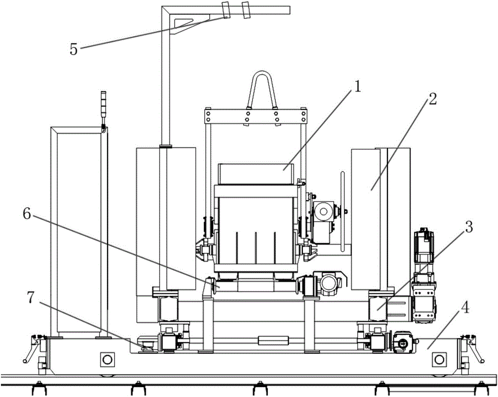
[0017] A fully automatic pouring machine, see figure 1 : It includes a ladle 1, the ladle 1 is supported on the tilting frame 2, and one side of the tilting frame 2 is connected with a ladle conveying roller table 6, and the ladle conveying roller table 6 is used for After the ladle 1 is transported to the tilting frame 2 in time or the spent ladle 1 is separated from the tilting frame 2 in time, the ladle 1 filled with molten iron is fixed on the bottom support of the tilting frame 2 seat, the bottom of the bottom support seat is provided with a traverse frame 3, and the bottom of the traverse frame 3 is provided with a longitudinal movement frame 4, and the positions of the traverse frame 3 and the longitudinal movement frame 4 support A load cell 7 is provided, and an optical sensor 5 is arranged directly above the tilting frame 2 when it is in a working state, and the optical sensor 5 is arranged aligned with the molten iron level in the ladle 1 .

[0018] The specific nu...


PUM


Abstract

The invention provides a full-automatic pouring machine. By using the full-automatic pouring machine, a mold cavity in a molding line can be quickly and accurately poured, and automatic pouring can be performed in the whole process, so that the degree of automation is high, time and labor are saved when personnel operate the pouring machine, and safe operation is guaranteed. The full-automatic pouring machine comprises a pouring ladle, wherein the pouring ladle is supported on an inclined rotating rack, a pouring ladle conveying roller way communicates with one side of the inclined rotating rack, the pouring ladle conveying roller way is used for conveying the pouring ladle to the inclined rotating rack in time or disengaging the used pouring ladle from the inclined rotating rack in time, the pouring ladle filled with molten iron is fixedly installed on a support seat at the bottom of the inclined rotating rack, a transverse moving rack is arranged at the bottom of the support seat at the bottom, a longitudinal moving rack is arranged at the bottom of the transverse moving rack, weighing sensors are arranged in positions of the transverse moving rack and the longitudinal moving rack, an optical sensor is arranged just above the inclined rotating rack when the inclined rotating rack is in a working condition, and the optical sensor is aligned with the liquid level of the molten iron in the pouring ladle.

Description

technical field [0001] The invention relates to the technical field of pouring machine structure, in particular to a fully automatic pouring machine, and the invention also provides a working method of the automatic pouring machine. Background technique [0002] In the pouring process of the existing pouring machine, manual intervention is required, and the pouring weight needs to be manually observed and calibrated by the workers during the pouring process. Because the high-temperature molten iron is placed in the ladle of the pouring machine, personnel are prone to danger during the operation, so The existing pouring machine has a low degree of automation, which leads to time-consuming and labor-intensive operations by personnel, and there is a great potential safety hazard. Contents of the invention [0003] In view of the above problems, the present invention provides a fully automatic pouring machine, which enables the pouring machine to quickly and accurately pour th...

Claims


Application Information

Patent Timeline
Patent Type & Authority Applications(China)
IPC IPC(8): B22D41/06
CPCB22D41/06
Inventor 余自
Owner SUZHOU SUZHU FOUNDRY MACHINERY MFG
Why Eureka
Try Eureka