
Prestretching mounting structure for screw rod

An installation structure and pre-stretching technology, applied in feeding devices, metal processing machinery parts, metal processing and other directions, can solve the problems of difficulty in ensuring pre-stretching effect, cumbersome operation, affecting bearing accuracy, etc.

Active Publication Date: 2016-11-09
广州市高品机床有限公司
View PDF5 Cites 8 Cited by
  • Summary
  • Abstract
  • Description
  • Claims
  • Application Information

AI Technical Summary

Problems solved by technology

[0003] In the pre-stretching structure installed on the screw rod of the existing machine tool, spacers are respectively arranged on both sides of the bearings at the two ends of the screw rod, and the spacers are compressed by tightening the nuts to realize the pre-stretching of the screw rod, and the pre-stretch amount is determined by The thickness of the septum is determined by adjusting the thickness of the septum to adjust the pre-stretch amount of the screw rod. Once the screw rod is installed, it is difficult to adjust the pre-stretch amount
In addition, due to the processing tolerance of spacers, screw rods, tightening nuts, bearings, bearing sleeves and other parts, as well as the problem of assembly accuracy, there will be deviations between the actual pre-stretching amount of the final screw rod and the designed pre-stretching amount , it is difficult to guarantee the pre-stretching effect
Once the pre-stretching fails to meet the requirements, it needs to be disassembled again for adjustment. It is very cumbersome to adjust the pre-tightening force, and the repeated assembly and disassembly of the bearing spacer will also affect the accuracy of the bearing.

Method used


Image

  • Prestretching mounting structure for screw rod
  • Prestretching mounting structure for screw rod
  • Prestretching mounting structure for screw rod

Examples


Embodiment Construction

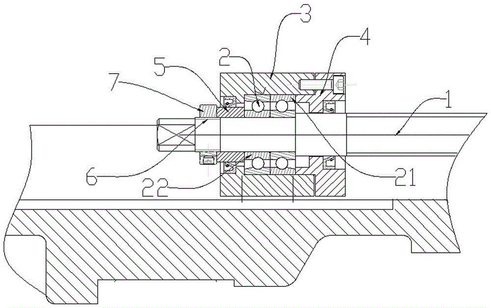
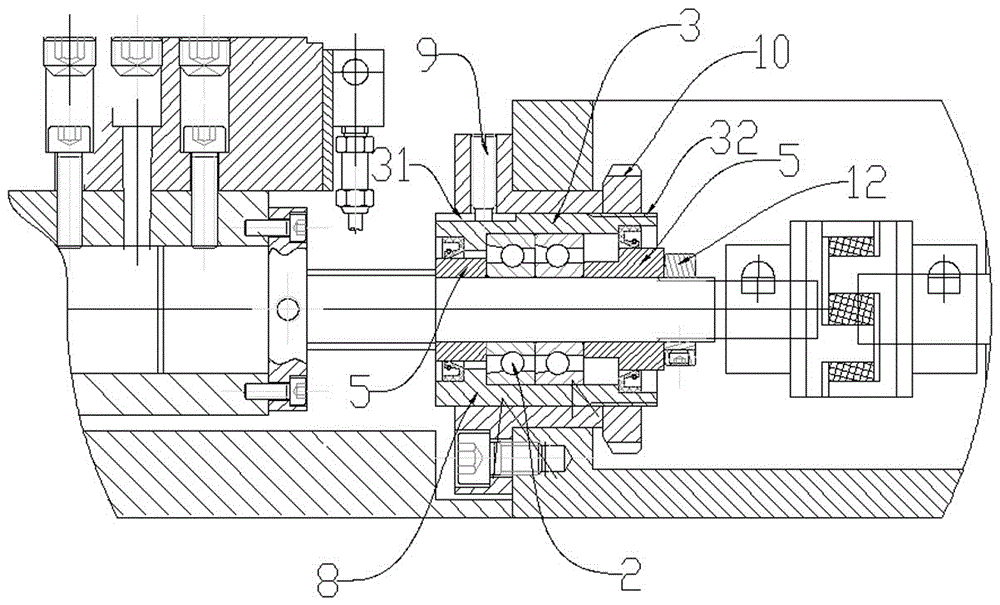
[0016] A screw rod pre-tensioning installation structure, such as figure 1 , One end of the screw rod 1 is fixed and the other end is free, and a bearing 2 is installed at both the fixed end and the free end. fixed end, such as figure 2 , the bearing 2 is placed in the bearing seat 3 fixed to the main structure of the machine tool, and the inner and outer sides of the bearing seat 3 are respectively provided with a gland 4 and an inner ring spacer 5, and the gland 4 is firmly connected with the bearing seat 3 , press against the outer ring 21 of the bearing from the inside, and the spacer 5 of the inner ring presses against the inner ring 22 of the bearing from the outside, and a threaded segment 6 is provided on the screw rod outside the spacer 5 of the inner ring, and the lock nut 7 is screwed on On it, the inner ring spacer 5 and the bearing inner ring 22 are pressed tightly. At the free end of screw rod 1, such as image 3 , the bearing sleeve 8 is installed outside th...


PUM


Abstract

The invention discloses a prestretching mounting structure for a screw rod. One end of the screw rod is fixed, and the other end of the screw rod is free; bearings are separately arranged at the fixed end and the free end; the bearing at the fixed end is arranged in a bearing block fixed with a machine tool main body structure; a bearing bush is arranged outside the bearing at the free end of the screw rod; a motor base connecting flange is arranged outside the bearing bush and is fixedly connected with a motor base; a through hole is formed in the motor base connecting flange; a longitudinal sliding chute is formed in a position, corresponding to the through hole, of the bearing bush; a thread section is arranged at the outer side of the bearing bush; a thread section part is located at the lower side of the motor base connecting flange; part of the thread section part extends from the outer side of the motor base connecting flange; and a bearing bush adjusting nut is screwed in the thread section. The bearing bush adjusting nut can screw in the thread section of the bearing bush by a certain distance, so that the prestretching amount of the screw rod can be controlled, further the control over the prestretching amount of the screw rod is conveniently realized, and the simplicity in operation is realized.

Description

technical field [0001] The invention relates to an installation structure of a screw rod of a machine tool, in particular to a pre-stretching installation structure of a screw rod of a machine tool. Background technique [0002] In the feed transmission system of the machine tool, the screw rod is often used as the transmission element to convert the rotary motion of the servo motor into the linear movement of the motion actuator (tool holder or table, etc.). However, the thermal elongation of the screw rod during the working process is unavoidable, because the thermal elongation of the screw rod will affect the movement accuracy of the actuator moving on it, which will have a negative impact on the machining accuracy of the machine tool. In the case of high precision requirements, in order to reduce the impact of the thermal expansion and deformation of the screw rod on the machining accuracy, it is necessary to compensate the thermal expansion of the screw rod, and the pre...

Claims


Application Information

Patent Timeline
IPC IPC(8): B23P19/04B23P19/10B23Q5/40
CPCB23P19/04B23P19/10B23Q5/40
Inventor 温展波沈诗剑
Owner 广州市高品机床有限公司
Learn More