Supercharge Your Innovation With Domain-Expert AI Agents!

An assembly mold for brake components of textile equipment

A technology for brake components and assembling molds, which is applied in textiles, textiles and papermaking, workpiece clamping devices, etc., can solve the problems of poor assembly effect and slow work efficiency, and achieve the effect of low cost, simple structure and easy promotion

Active Publication Date: 2018-01-09
苏州利达铸造有限公司
View PDF7 Cites 0 Cited by
  • Summary
  • Abstract
  • Description
  • Claims
  • Application Information

AI Technical Summary

Problems solved by technology

At present, the assembly of these parts is usually carried out under manual conditions, the work efficiency is slow and the assembly effect is poor

Method used


Image

  • An assembly mold for brake components of textile equipment
  • An assembly mold for brake components of textile equipment

Examples


Embodiment Construction

[0015] The preferred embodiments of the present invention will be described in detail below with reference to the accompanying drawings.

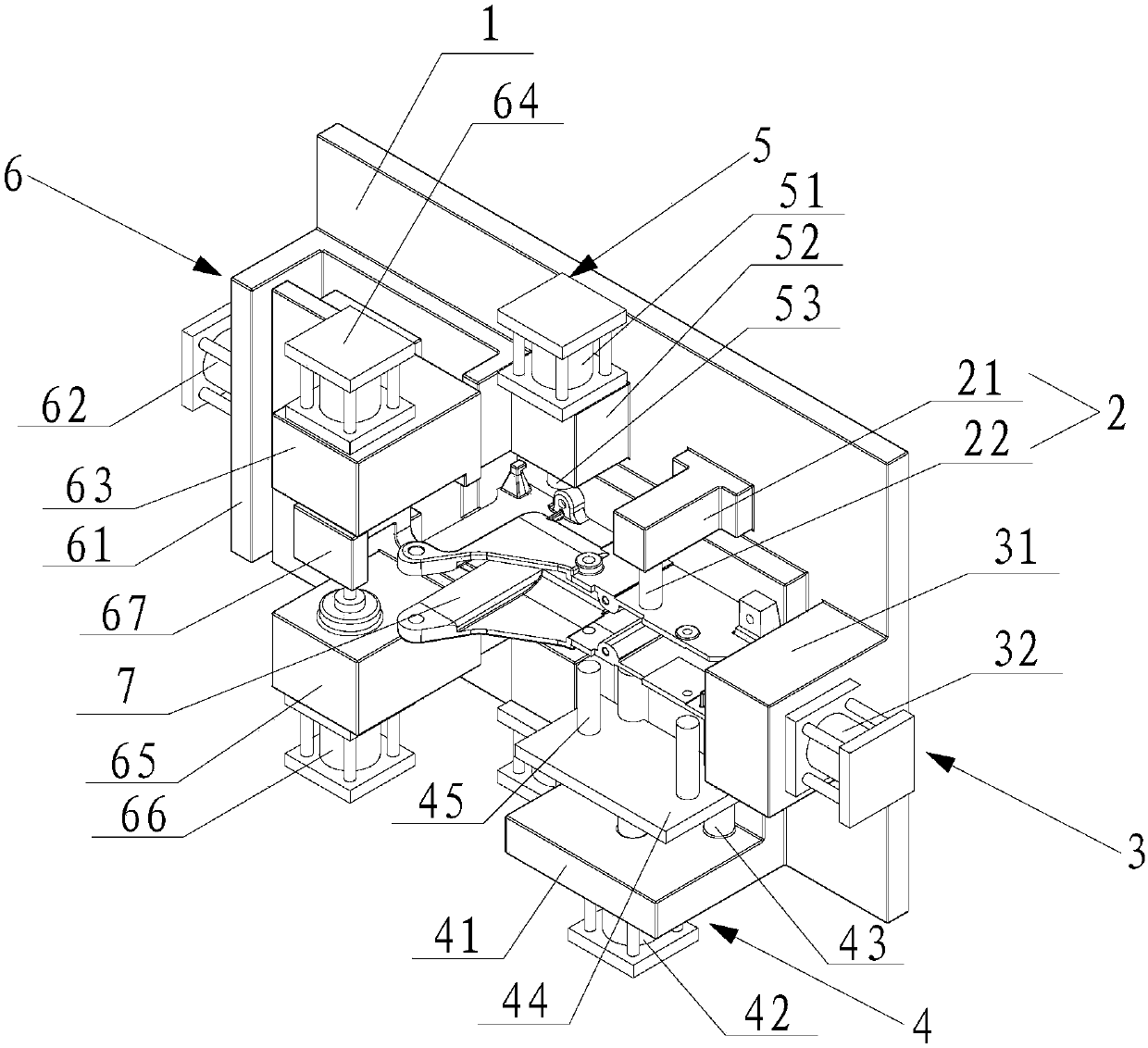
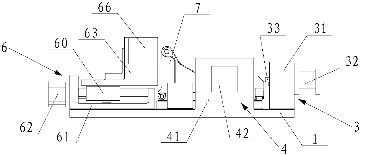
[0016] Such as figure 1 with figure 2 The illustrated assembly mold of the brake assembly of the textile equipment mainly includes a base plate 1, a limit mechanism 2, a first cylinder assembly 3, a third cylinder assembly 6, and the like.

[0017] Among them, the first cylinder assembly 3 is fixed on the base plate 1 to resist the end of the brake assembly 7; the limiting mechanism 2 is fixed on the base plate 1 to position the side of the brake assembly 7; the second cylinder assembly 4 The third cylinder assembly 6 is fixed on the base plate 1 and used to press against the other side of the brake assembly 7; the third cylinder assembly 6 is fixed on the base plate 1 and used to press against the other end of the brake assembly 7.

[0018] Wherein, the first cylinder assembly 3 includes a first support block 31 fixed on the base plate 1, a fir...


PUM


Abstract

The invention relates to an assembly jig for a brake assembly of spinning equipment. The assembly jig comprises a base plate, a first cylinder assembly fixed on the base plate and used for propping against an end part of the brake assembly, a limiting mechanism fixed on the base plate and used for positioning the side surface of the brake assembly as well as a third cylinder assembly fixed on the base plate and used for propping against the other end of the brake assembly. Through cooperation of the first cylinder assembly, the limiting mechanism, the second cylinder assembly and the third cylinder assembly, the brake assembly can be clamped and accurately positioned, and the assembly jig is simple in structure, lower in cost and easy to popularize and facilitates automatic assembling.

Description

Technical field [0001] The invention relates to an assembly mold, in particular to an assembly mold of a brake component of a textile equipment. Background technique [0002] Looms can be classified into shuttle looms and shuttleless looms according to the weaving method. Shuttle looms are looms that use traditional shuttle weft insertion. The shuttle is large in size and heavy in weight. It is repeatedly projected back and forth. The machine has high vibration, high noise, slow speed and low efficiency. The shuttleless loom is a new type of loom born after the shuttle loom. Shuttleless looms quickly occupied the loom market due to its light weight, low vibration, low noise, fast speed, and high efficiency. The speed of shuttleless looms is high, and the efficiency is usually 4-8 times higher than that of shuttle looms. Therefore, shuttleless looms are vigorously promoted. Shuttleless looms mainly include water jet looms, air jet looms, rapier looms, etc. In the work process,...

Claims


Application Information

Patent Timeline
Patent Type & Authority Patents(China)
IPC IPC(8): B25B11/02D03D51/00
CPCB25B11/02D03D51/00
Inventor 季吉清
Owner 苏州利达铸造有限公司
Features
  • R&D
  • Intellectual Property
  • Life Sciences
  • Materials
  • Tech Scout
  • Unparalleled Data Quality
  • Higher Quality Content
  • 60% Fewer Hallucinations
Learn More