
Self-positioning type pour plug

A self-positioning and bolting technology, applied in the field of rubber vulcanization, can solve the problems of inconsistent expansion and contraction speed, uneven heating of the mold, and jamming of the injection plug. Effect

Active Publication Date: 2016-11-09
安徽宁国中鼎模具制造有限公司
View PDF3 Cites 0 Cited by
  • Summary
  • Abstract
  • Description
  • Claims
  • Application Information

AI Technical Summary

Problems solved by technology

However, due to the need for heating during the vulcanization process of the rubber, as well as the cooling during the mold opening process and the uneven heating of the mold, the expansion and contraction speeds of the injection plug and the cup are inconsistent, and the injection plug is often stuck.
The injection plugs in the prior art are all fixedly arranged on the injection plug plate. Since there are guide posts for positioning on the injection plug plate, the positioning between the plunger plate and the mold is over-positioned, causing the injection plug to be stuck. The phenomenon is more exacerbated, this phenomenon is especially serious on multi-injection plug molds

Method used


Image

  • Self-positioning type pour plug
  • Self-positioning type pour plug

Examples


Embodiment Construction

[0019] In order to make the purpose, technical solutions and advantages of the embodiments of the present invention more clear, specific embodiments will be described in detail below with reference to the accompanying drawings.

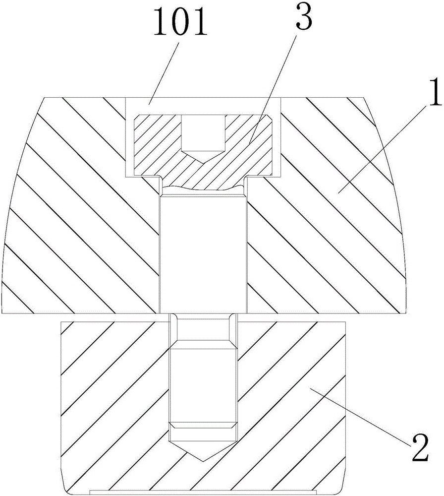
[0020] Such as Figure 1-2 as shown, figure 1 It is a structural schematic diagram of the present invention, figure 2 for figure 1 Partial enlarged view of A in , including plug plate 1, plug 2 and bolt 3.

[0021] The plug plate 1 is provided with a plurality of first holes 101, and in practice, the first holes 101 are stepped holes. The first end of the bolt 3 passes through the first hole 101 and is connected with the injection plug 2 . During specific implementation, the bolts are shoulder bolts. Since the middle part of the shoulder bolt has no thread, the contact surface with the inner wall of the first hole 101 is relatively smooth, so that the resistance of the injection plug 2 during the automatic adjustment process is relatively small....


PUM


Abstract

The invention discloses a self-positioning type pour plug. The self-positioning type pour plug comprises a pour plug plate, pour plug bodies and bolts. The pour plug plate is provided with a plurality of first holes, and the first ends of the bolts penetrate through the first holes and are connected with the pour plug bodies. The aperture of the first holes is 0.1-0.5 mm larger than the diameter of rod parts of the bolts. A movable clearance is reserved between each pour plug body and the pour plug plate. The pour plug bodies can be in clearance fit with material cups on molds. The self-positioning type pour plug can effectively prevent the phenomenon that the pour plug bodies get stuck, thereby being beneficial for improving production efficiency.

Description

technical field [0001] The invention relates to the technical field of rubber vulcanization, in particular to a self-positioning injection plug. Background technique [0002] Injection plugs and cups are common tools in the production process of injection rubber molds. They are used in the injection production of ordinary vulcanizing machines. They have a simple structure and are easy to use. However, due to the need for heating during the vulcanization process of the rubber, as well as the cooling during the mold opening process and the uneven heating of the mold, the expansion and contraction speeds of the injection plug and the cup are inconsistent, and the injection plug is often stuck. The injection plugs in the prior art are all fixedly arranged on the injection plug plate. Since there are guide posts for positioning on the injection plug plate, the positioning between the plunger plate and the mold is over-positioned, causing the injection plug to be stuck. The pheno...

Claims


Application Information

Patent Timeline
Patent Type & Authority Applications(China)
IPC IPC(8): B29C35/02
CPCB29C35/02
Inventor 张镔陈增宝韩双轮朱静
Owner 安徽宁国中鼎模具制造有限公司
Learn More