Film blowing machine with improved winding mechanism

A technology of winding mechanism and film blowing machine, which is applied in the direction of winding strips, thin material processing, transportation and packaging, etc. It can solve the problem that there is no other guide for film winding, film blowing machine occupies a large space, and reduces film production efficiency and other problems, to reduce the probability of tearing, avoid uneven melting, improve wrinkle resistance and firmness

Active Publication Date: 2016-11-09
ZHEJIANG SHANGCHENG SCI&TECH
View PDF13 Cites 13 Cited by
  • Summary
  • Abstract
  • Description
  • Claims
  • Application Information

AI Technical Summary

Problems solved by technology

The film is prone to offset during winding, which will cause the film to fold and produce wrinkles. There is a large misalignment between the upper and lower layers of the film roll, especially in the early stage of winding. When the film roll is directly small, the film roll There is no other guide for the roll. If the deviation is found in time, it can be corrected manually, but this reduces the production efficiency of the film to a certain extent.
[0004] Secondly, before the winding shaft, there is also a conveying roller for conveying the film. If the two do not cooperate properly, the winding will not be tight or the film will be damaged due to excessive tension.
[0005] In addition, before winding the film, it needs to be flattened by a guide roller with a flattening function, so the film blowing machine needs to occupy a large space

Method used


Image

  • Film blowing machine with improved winding mechanism
  • Film blowing machine with improved winding mechanism
  • Film blowing machine with improved winding mechanism

Examples


Embodiment Construction

[0030] The following are specific embodiments of the present invention and in conjunction with the accompanying drawings, the technical solutions of the present invention are further described, but the present invention is not limited to these embodiments.

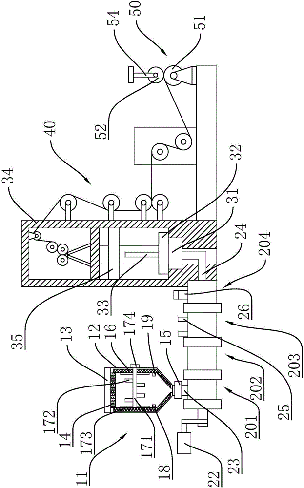
[0031] Such as Figure 1 to Figure 4 As shown, the present invention provides a film blowing machine with an improved winding mechanism 50, including an extrusion mechanism, a film blowing mechanism, a traction mechanism 40 and a winding mechanism 50, and the film blowing mechanism includes a die head 31, an air ring 32 And frame 34, air ring 32 is arranged on the top of die head 31, and die head 31 and air ring 32 are respectively fixed on the lower end of frame 34, and traction mechanism 40 is arranged on the upper end of frame 34, and extruding mechanism has discharge port 24, the discharge port 24 is connected to the die head 31; the winding mechanism 50 includes a reel 51, a belt and a motor for rewinding the film, th...


PUM


Abstract

The invention provides a film blowing machine with an improved winding mechanism. Th film blowing machine comprises an extrusion mechanism, a film blowing mechanism, a traction mechanism and the winding mechanism. The film blowing mechanism comprises a die head, an air ring and a rack. The air ring is arranged on the die head. The die head and the air ring are fixedly arranged at the lower end of the rack. The traction mechanism is arranged at the upper end of the rack. The extrusion mechanism is provided with a discharge outlet connected with the die head. The winding mechanism comprises a winding shaft, a belt and a motor, wherein the winding shaft is used for winding thin films. The motor is in transmission connection with the winding shaft through the belt. The thin films blown out from the die head are conveyed to the winding shaft through the traction mechanism. A press shaft capable of pressing the thin films is arranged above the winding shaft. The winding mechanism further comprises a support frame and elastic suspended arms. The press shaft is connected to the support frame through the elastic suspended arms. According to the film blowing machine with the improved winding mechanism, deviation of the thin films in the winding process can be avoided, and dislocation of an upper layer and a lower layer of a thin film is prevented.

Description

technical field [0001] The invention belongs to the technical field of plastic films, and relates to a film blowing machine, in particular to a film blowing machine with an improved winding mechanism. Background technique [0002] The film production mainly adopts a film blowing machine. The raw material is heated into a molten state through an extrusion mechanism and extruded, and the film bubble is blown out by compressed air to make a film, and finally wound into a cylinder through a winding mechanism. [0003] The film winding structure used in the existing film blowing machines generally includes a frame and a winding roller. The winding roller is driven by a motor to wind the film. The winding effect of the film depends entirely on the rotation of the winding roller. The film is prone to offset during winding, which will cause the film to fold and produce wrinkles. There is a large misalignment between the upper and lower layers of the film roll, especially in the earl...

Claims


Application Information

Patent Timeline
Patent Type & Authority Applications(China)
IPC IPC(8): B29C55/28B29C35/02B29B13/06B29B13/10B65H18/26
CPCB29B13/065B29B13/10B29C35/02B29C55/28B65H18/26
Inventor 张伟忠苏跃锋施叶标汪琴伟
Owner ZHEJIANG SHANGCHENG SCI&TECH
Why Eureka
Try Eureka