A powder spraying device for a printing machine

A printing machine and powder spraying technology, applied to printing machines, general parts of printing machinery, printing, etc., can solve problems such as increased production costs, too thick powder layer, easy ink adhesion, etc., to accelerate cooling speed and reduce use The effect of ensuring dryness

Inactive Publication Date: 2018-03-30
湖南天成印务有限公司
View PDF14 Cites 1 Cited by
  • Summary
  • Abstract
  • Description
  • Claims
  • Application Information

AI Technical Summary

Problems solved by technology

In order to improve the printing efficiency, at present, the printed paper is usually wound together without air drying, which will cause the printed matter to adhere to the back of the printed matter, and the printing quality will also be affected. In order to solve this problem , the technician chooses to spray a layer of powder before the printed matter is wound, so that the surface of the printed matter is smooth and has no adhesion ability, but the thickness of the ink layer on the surface of some printed matter is different, and the existing technology adopts uniform powder spraying Thickness, resulting in some parts of the powder layer being too thick, which will have a certain impact on the printed matter, while some parts still have a certain adhesion ability due to the too thin powder layer, and the ink is easy to adhere to the contact with it during the winding process. On the paper, it will cause distortion of the printed matter and affect the effect of printing
At the same time, because not all the powder can adhere to the paper during the powder spraying process, a large amount of powder is needed, and these powders will not only affect the environment, but also have a certain impact on the health of workers, and will also cause waste and increase production. cost
Therefore, the existing technology has the problems of being unable to adjust the thickness of the powder layer in real time during the powder spraying process, poor powder spraying effect, polluting the environment, affecting the health of workers, and high production costs.

Method used


Image

  • A powder spraying device for a printing machine
  • A powder spraying device for a printing machine

Examples


Embodiment Construction

[0013] The present invention will be further described below in conjunction with the drawings and embodiments, but it will not serve as a basis for limiting the present invention.

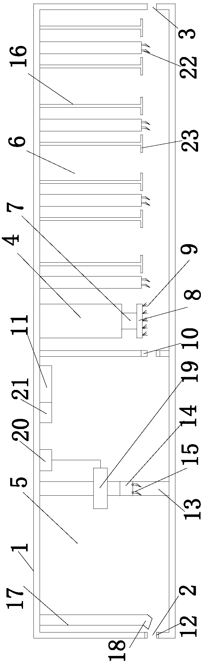
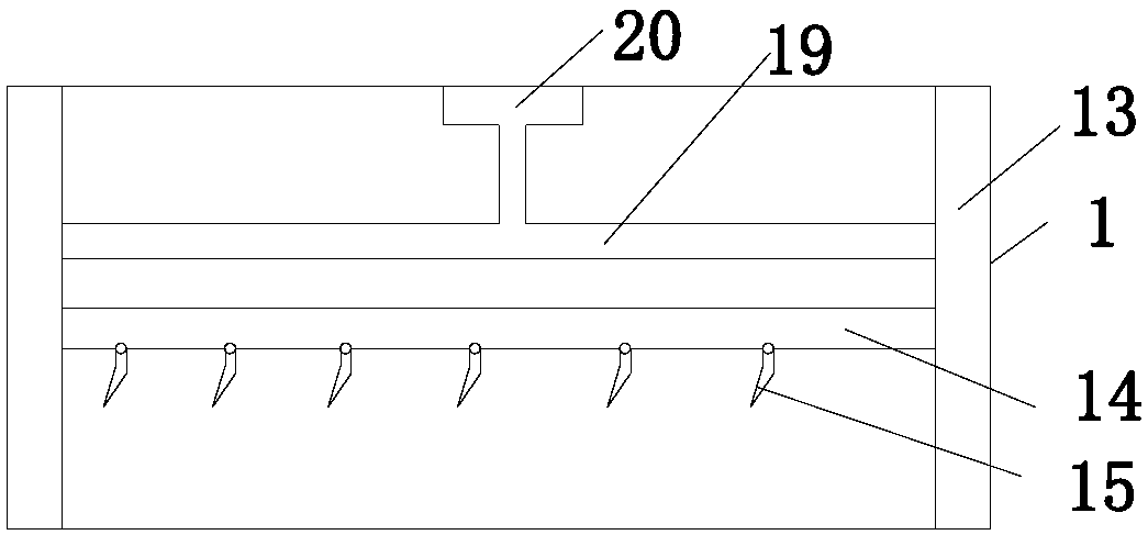
[0014] Examples. A powder spraying device for a printing machine, which is composed as figure 1 with figure 2 As shown, the housing 1 is included. One side of the housing 1 is provided with a paper inlet 2, and the other side of the housing 1 is provided with a paper outlet 3. The housing 1 is provided with a partition 4, and one side of the partition 4 is a spray nozzle. The powder chamber 5, the other side of the partition 4 is the dust removal chamber 6, the hydraulic rod 7 is provided under the partition 4, the lower end of the hydraulic rod 7 is provided with a brush fixing rod 8, and the brush fixing rod 8 is provided with a brush 9; The powder spraying chamber 5 is provided with a thickness sensor 10 on the side close to the partition 4, the thickness sensor 10 is connected with a controller ...


PUM


Abstract

The invention discloses a powder spraying device of a printing machine. The powder spraying device of the printing machine comprises a shell (1), wherein a baffle plate (4) is arranged in the shell (1); one side of the baffle plate (4) is provided with a powder spraying chamber (5); the other side of the baffle plate (4) is provided with a dust removing chamber (6); one side, which approaches the baffle plate (4), of the powder spraying chamber (5) is provided with a thickness sensor (10); the thickness sensor (10) is connected with a controller (11), a sliding track (13) is arranged in the powder spraying chamber (5); the sliding track (13) is provided with a powder conveying pipe (14); the lower part of the powder conveying pipe (14) is provided with spraying nozzles (15); the spraying nozzles (15) are connected with the controller (11). The powder spraying device of the printing machine has the characteristics that the thickness of a powder layer can be regulated in real time in a powder spraying process; the powder spraying effect is improved; the pollution to an environment is reduced; the influence on the physical health of a worker is decreased; the production cost is decreased.

Description

Technical field [0001] The invention relates to a printing machine component, in particular to a powder spraying device of the printing machine. Background technique [0002] With the continuous development and progress of society, the demand for printed products is also expanding, and the content of printed products is becoming more and more abundant. Different printed products require different inks, and the adhesion and adhesion of different inks The abilities are also different. In order to improve the efficiency of printing, currently the printed paper is usually rolled together without air-drying. This will cause the printed matter to adhere to the back of the printed matter, and the printing quality will also be affected. In order to solve this problem , The technician chooses to spray a layer of powder before the printed matter is wound, so that the surface of the printed matter is smooth and has no adhesion ability, but the thickness of the ink layer on the surface of s...

Claims


Application Information

Patent Timeline
Patent Type & Authority Patents(China)
IPC IPC(8): B41F23/06
CPCB41F23/06
Inventor 林礼区
Owner 湖南天成印务有限公司
Why Eureka
Try Eureka