Vertical lift multi-rotor aircraft and horizontal lift fixed-wing aircraft
A vertical lift and horizontal lift technology, applied in the field of fixed-wing aircraft, can solve the problems of large lateral force area, danger, and difficult control of the fixed wing, and achieve good control, reduce impact, and increase the effect of wing surface area
- Summary
- Abstract
- Description
- Claims
- Application Information
AI Technical Summary
Problems solved by technology
Method used
Image

Examples
Embodiment 1
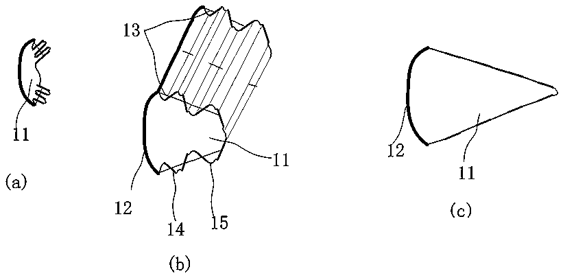
[0041] figure 1 (a) indicates that the wing airbag 11 is in a retracted folded state, figure 1 (b) indicates that the wing airbag 11 is in the inflated and opened state, figure 1 (c) shows that the wing airbag 11 is fully opened.
[0042] Such as figure 1 As shown, the aircraft fixed wing in this embodiment comprises a rigid fixed wing leading edge 12, and the rear side of the fixed wing leading edge 12 is provided with a wing airbag 11 that can be retracted. In the airbag mounting bracket on the wing leading edge, the airbag mounting bracket can be integrally arranged with the fixed wing leading edge or fixedly assembled separately, and the expanded and opened wing airbag 11 forms the airbag wing part joined with the fixed wing leading edge. This kind of wing airbag 11 is a folding airbag, which realizes the expansion-retraction of the wing airbag by opening-folding. The connecting part 14 is not stretchable, while the flexible folding part 15 is stretchable.
[0043] It...
Embodiment 2
[0048] Its difference with aircraft fixed-wing embodiment 1 mainly lies in: as figure 2 As shown, in aircraft fixed-wing embodiment 2, there are two wing airbags arranged along the span direction of the fixed wing, which are respectively an inner airbag 21 and an outer airbag 22. The two wing airbags are distributed independently of each other, and each wing airbag passes through The guiding structure 20 whose guiding direction is along the chord direction of the fixed wing performs an expansion-retraction action along the chord direction of the fixed wing. During specific implementation, slip rings 23 or bearings can be arranged on the wing airbags to be assembled correspondingly with the guide structure, so as to ensure normal sliding of the wing airbags along the guiding direction of the guide structure.
[0049] Moreover, in this embodiment, both the inner airbag 21 and the outer airbag 22 include a bladder made of elastic material, and the expansion degree of the bladder...
Embodiment 3
[0053] Its difference with aircraft fixed-wing embodiment 2 mainly lies in: as image 3 As shown, in the aircraft fixed wing embodiment 3, the two independent wing airbags arranged along the span direction of the fixed wing all perform expansion-retraction actions along the span direction of the fixed wing. In fact, there are corresponding A guiding structure for guiding the expansion and retraction of wing airbags, the guiding direction of the guiding structure is the span direction of the fixed wing.
[0054] In the present embodiment, the inside airbag 31 and the outside airbag 32 are included here, and the two airbags are distributed along the span direction of the fixed wing, and expand-retract along the span direction of the fixed wing. The balloon body can control the expansion degree of the balloon body by filling the balloon body with gases of different pressures. Such as image 3 The degree of expansion of the outer airbag 32 in (a) is different from that in 3(b), ...
PUM
 Abstract
Description
Claims
Application Information
 - R&D
- Intellectual Property
- Life Sciences
- Materials
- Tech Scout
- Unparalleled Data Quality
- Higher Quality Content
- 60% Fewer Hallucinations
Browse by: Latest US Patents, China's latest patents, Technical Efficacy Thesaurus, Application Domain, Technology Topic, Popular Technical Reports.
© 2025 PatSnap. All rights reserved.Legal|Privacy policy|Modern Slavery Act Transparency Statement|Sitemap|About US| Contact US: help@patsnap.com