Bionic folding unmanned aerial vehicle using flexible airfoil

A technology using flexible and unmanned aerial vehicles, applied in the directions of unmanned aerial vehicles, wings, motor vehicles, etc., can solve the problems of insufficient maneuverability of aircraft, small wing area, difficult reconnaissance operations, etc., to improve flexibility, Large wing area, the effect of reducing flight speed

Active Publication Date: 2021-07-27
BEIHANG UNIV
View PDF13 Cites 0 Cited by
  • Summary
  • Abstract
  • Description
  • Claims
  • Application Information

AI Technical Summary

Problems solved by technology

Most of the existing folding micro-UAVs are in a large aspect ratio configuration, so that the wings are retracted to coincide with the fuselage, such as the gray partridge UAV in the United States. In the case of limited size, the wing area is small, which also leads to a large aspect ratio of the aircraft wing, a large minimum level flight speed, and insufficient maneuverability of the aircraft
At the same time, the Reynolds number of the micro-UAV itself is low, resulting in low aerodynamic efficiency, making it difficult to carry out more detailed reconnaissance operations, etc.

Method used


Image

  • Bionic folding unmanned aerial vehicle using flexible airfoil
  • Bionic folding unmanned aerial vehicle using flexible airfoil
  • Bionic folding unmanned aerial vehicle using flexible airfoil

Examples


Embodiment Construction

[0041] The technical solutions in the embodiments of the present invention will be clearly and completely described below in conjunction with the accompanying drawings in the embodiments of the present invention. Obviously, the described embodiments are only for illustration and are not intended to limit the present invention.

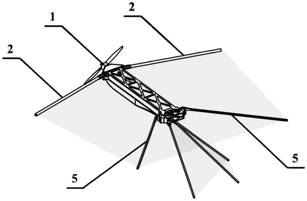
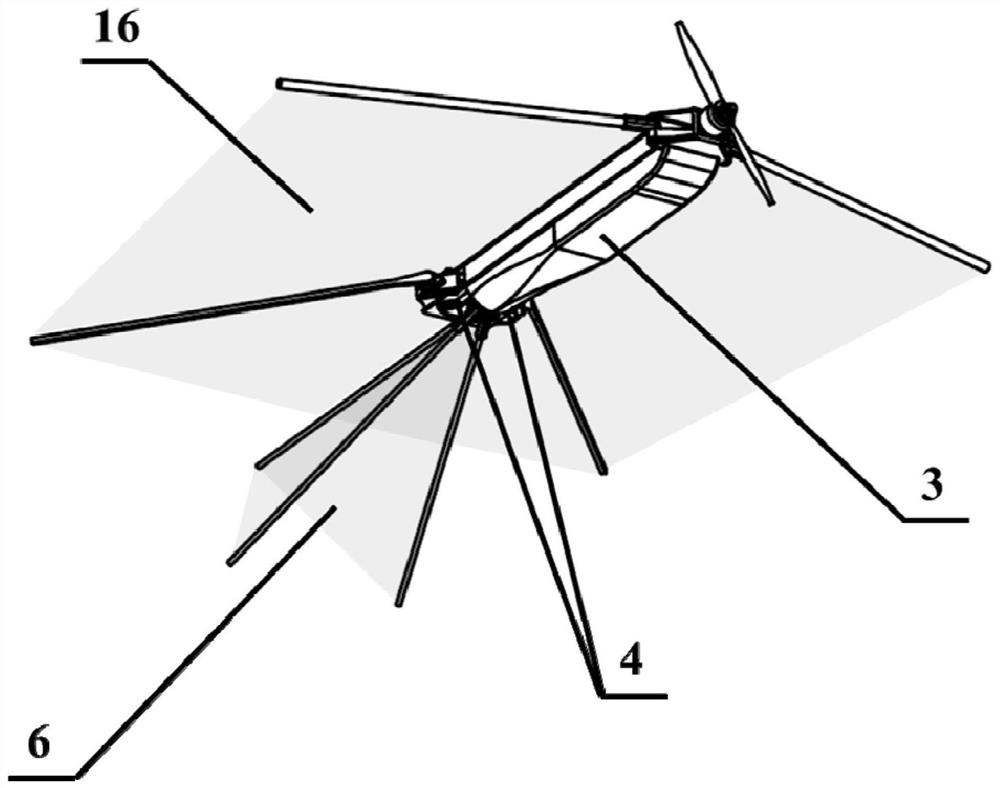
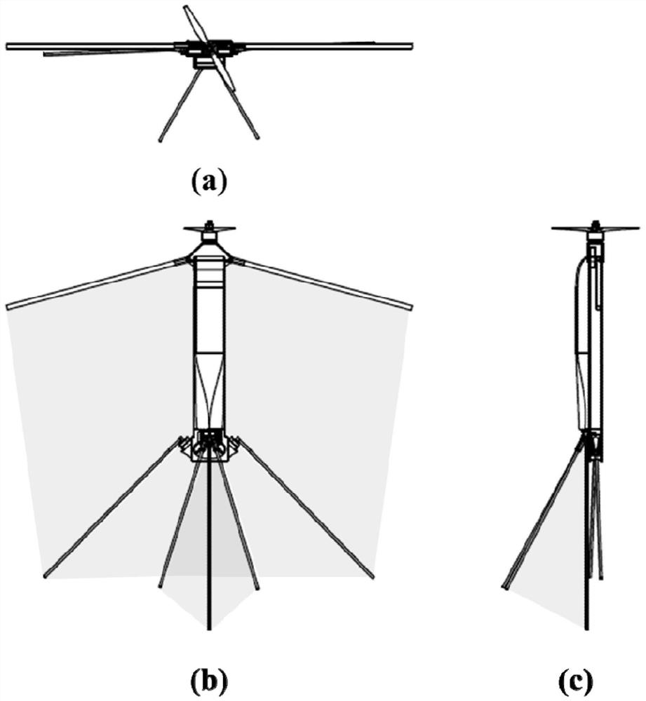
[0042] The invention proposes a bionic folding UAV using a flexible wing surface. The typical size is a wingspan of 200-600mm, the flight weight of the UAV is about 150-600g, and the typical length is 200-600mm. After folding, it can be stored in a In a cuboid with a side length of no more than 40mm*70mm, the cruise speed of the aircraft is about 10m / s-20m / s, and the flight time is about 30min. It can be used for reconnaissance and strike missions carried by individual soldiers, and can also be used for long-distance airdrop combat missions of small and medium-sized UAVs.

[0043] Such as Figure 1-3 As shown, the structure of the bionic folding UAV usi...


PUM


Abstract

The invention discloses a bionic folding unmanned aerial vehicle using flexible airfoils and a using method thereof, which belong to the technical field of miniature unmanned aerial vehicles. The specific structure of the unmanned aerial vehicle comprises a micro power system, a wing leading edge, a main fuselage, a servo mechanism, a foldable control surface control mechanism, a V-shaped empennage and a flexible wing surface. The micro power system is fixed at the front end of the main fuselage; the left side and the right side of the front end of the main fuselage are each provided with a foldable wing leading edge, and the left side and the right side of the rear end of the main fuselage are each provided with a foldable control surface control mechanism controlled by a servo mechanism. And the foldable V-shaped empennage is arranged at the tail end of the main fuselage. After the unmanned aerial vehicle pops up, the wing leading edge, the unmanned aerial vehicle foldable control surface control mechanism and the V-shaped empennage are automatically opened under the elastic effect, so that the flexible wing surface is unfolded. The flexible airfoil design is adopted, so that the folding unmanned aerial vehicle can obtain a larger wing area and higher aerodynamic efficiency, the lift coefficient is improved, the minimum level flight speed of the unmanned aerial vehicle is reduced, and the folding unmanned aerial vehicle has better maneuverability.

Description

technical field [0001] The invention relates to the technical field of micro drones, in particular to a bionic folding drone using flexible wings. Background technique [0002] With the continuous expansion of UAV market demand and the continuous development of UAV technology, the miniaturization of UAV has become one of the important development directions in this field. [0003] As a category of unmanned aerial vehicles, Micro Air Vehicle (MAV) was first proposed by the US Defense Advanced Research Projects Agency (DARPA) at the Future Military Conference in 1992. At that time, DARPA defined MAV as: the flight speed of MAV is about 5-20m / s, and the maximum design length of its fuselage is between 10-15cm, which is about the size of an adult's palm. With the development of science and technology and in-depth research on actual use, the U.S. military has gradually relaxed the size restrictions on micro air vehicles, and has higher requirements for the functions and practica...

Claims


Application Information

Patent Timeline
Patent Type & Authority Applications(China)
IPC IPC(8): B64C31/024B64C31/02B64C3/00
CPCB64C31/024B64C31/02B64C3/00B64U70/70B64U30/12B64U2101/00
Inventor 胡天翔唐元祎王金瀚葛云松唐浩楠吴成岳屈秋林
Owner BEIHANG UNIV
Why Eureka
Try Eureka