Deep hole machining manipulator

A manipulator and deep hole technology, which is applied in the field of hole processing, can solve the problems of easy vibration, ripple and taper, large depth-to-diameter ratio, high processing accuracy and surface quality requirements, to ensure processing accuracy and surface quality, and reduce tool size. The effect of high aspect ratio and high tool strength

Inactive Publication Date: 2013-05-01
CHONGQING TECH & BUSINESS INST
View PDF12 Cites 13 Cited by
  • Summary
  • Abstract
  • Description
  • Claims
  • Application Information

AI Technical Summary

Problems solved by technology

[0002] Traditional hole processing is generally carried out on lathes or drilling machines. By clamping tools such as drills, boring tools or reaming drills on the tool holder of the lathe or drilling machine, the processing of conventional holes such as drilling, boring and reaming can be realized. When processing deep holes, due to the limitation of the hole diameter, the tool holder is small in diameter, large in length, poor in rigidity, and low in strength. It is prone to vibration, ripples and tapers during cutting, which affects the straightness and surface roughness of deep holes. In most cases, The depth-to-diameter ratio of lower deep holes is as high as L / d≥100, such as cylinder holes, axial oil holes of shafts, etc. These holes not only have a large depth-to-diameter ratio, but also require high machining accuracy and surface quality. It is difficult to meet the processing accuracy and quality requirements in processing such deep holes; not only that, it is also difficult to realize the splines in deep holes, curved structures in holes, spiral grooves in deep holes and curved teeth in inner cavities with traditional hole processing equipment. Processing and deep hole detection, resulting in the inability of the deep hole parts with the above structure to be processed into one piece and detect its internal surface quality, which has become a major problem in the field of deep hole processing

Method used


Image

  • Deep hole machining manipulator
  • Deep hole machining manipulator
  • Deep hole machining manipulator

Examples


Embodiment Construction

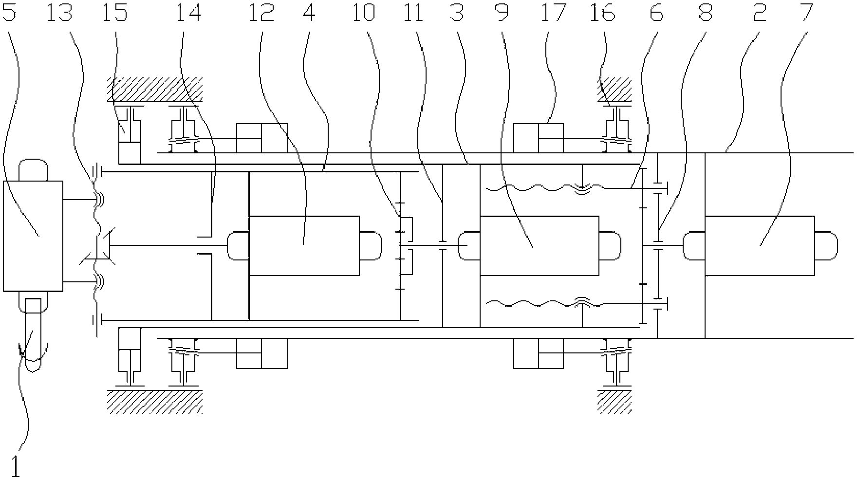
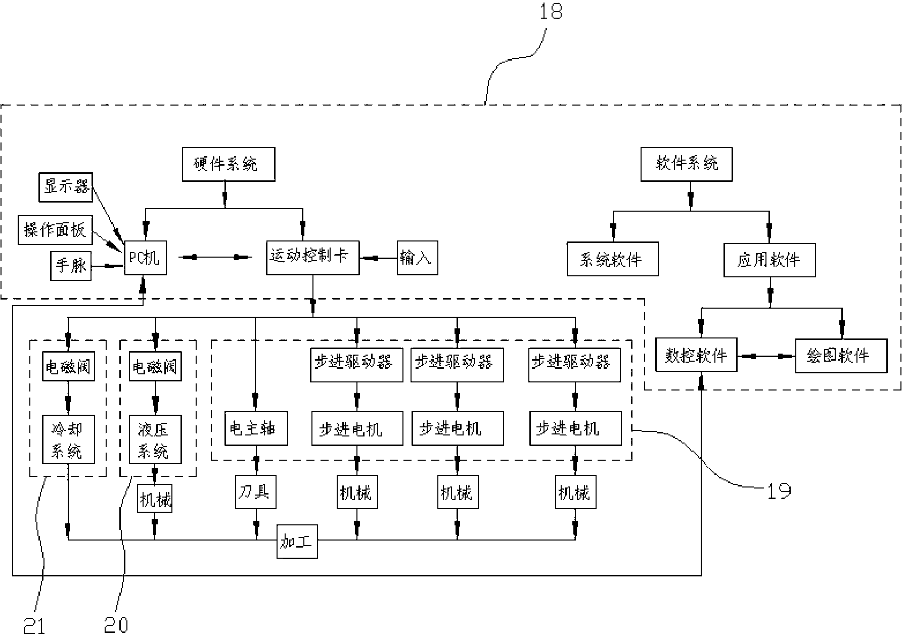
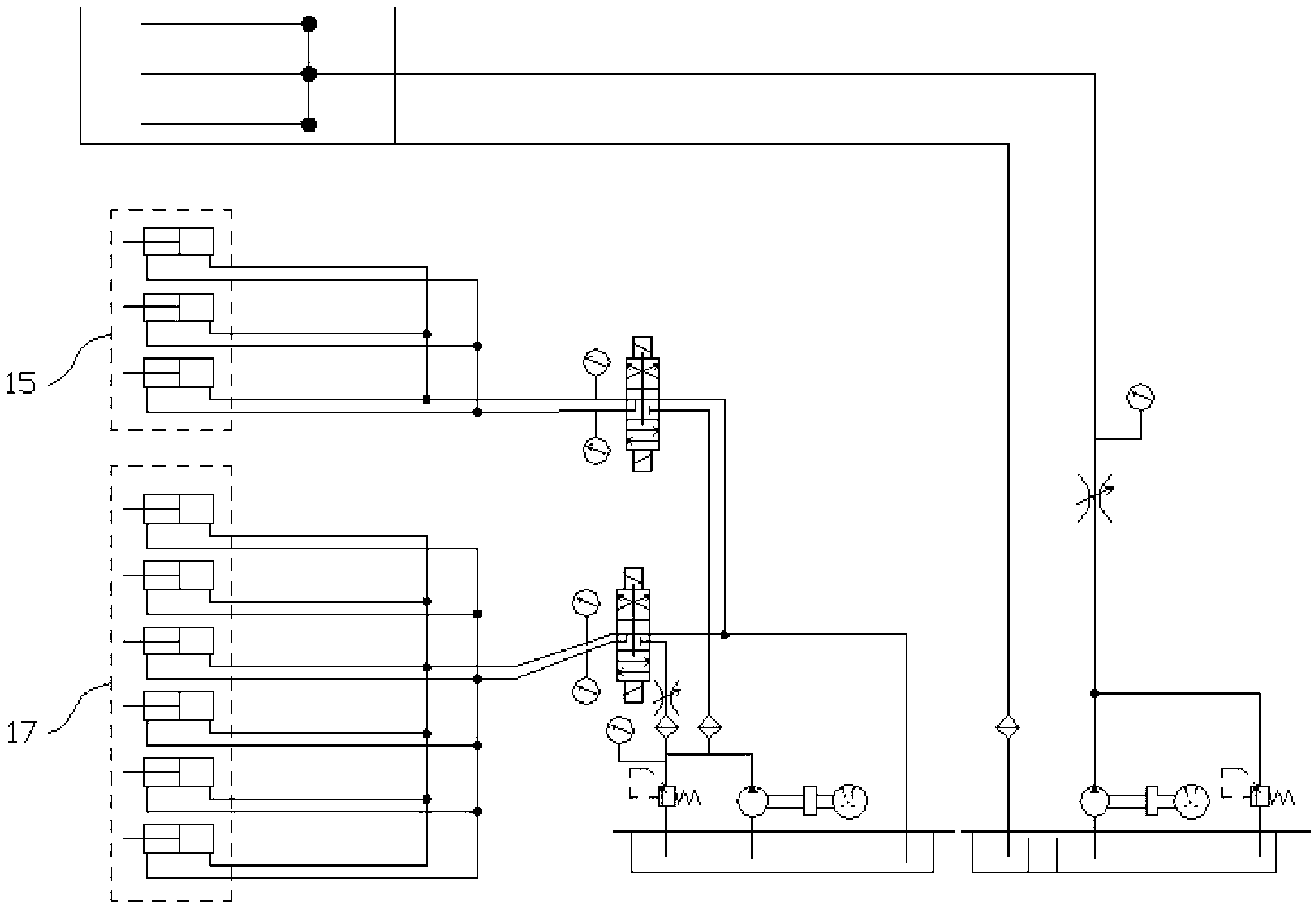
[0021] figure 1 It is the mechanical schematic diagram of the present invention, figure 2 It is a block diagram of the control system of the present invention, image 3 It is the hydraulic principle diagram of the present invention, as shown in the figure: the deep hole processing manipulator of this embodiment includes at least an arm assembly that can provide axial feed and circumferential feed, and a machine tool that is fixed at the output end of the arm assembly. The working device 1 for processing or detection and the control system for controlling the feeding direction of the arm assembly and the working state of the working device 1; the arm assembly includes a fixed arm 2, which is slidably connected to the fixed arm 2 with an axial single degree of freedom The telescopic arm 3, the rotary arm 4 connected to the telescopic arm 3 with a single degree of freedom in the circumferential direction, the fixed seat 5 for fixing the working device 1 installed and positioned...


PUM


Abstract

The invention discloses a deep hole machining manipulator, which comprises an arm assembly, a working device and a control system, wherein the arm assembly can be used for at least providing axial feed and peripheral feed; the working device is fixed at the output end of the arm assembly, and is used for machining or detecting; the control system is used for controlling the feeding direction of the arm assembly and the working state of the working device; and the arm assembly comprises a fixed arm, a telescopic arm which is axially connected to the fixed arm at a single degree of freedom in a sliding way, and a rotating arm which is circumferentially connected to the telescopic arm at a single degree of freedom. Due to the adoption of the deep hole machining manipulator disclosed by the invention, deep hole machining and detecting can be performed by breaking through the limit of a deep hole aperture, the length-diameter ratio of a tool can be reduced greatly, the tool has high strength and high rigidity, the deep hole machining accuracy and surface quality can be ensured, the machining requirements of special structures such as inner splines machined in deep holes, in-hole curve structures, inner spiral grooves, and curved teeth are met, and integral machining and forming of deep hole parts having the special structures are realized.

Description

technical field [0001] The invention relates to hole processing technology, in particular to a deep hole processing manipulator. Background technique [0002] Traditional hole processing is generally carried out on lathes or drilling machines. By clamping tools such as drills, boring tools or reaming drills on the tool holder of the lathe or drilling machine, the processing of conventional holes such as drilling, boring and reaming can be realized. When processing deep holes, due to the limitation of the hole diameter, the tool holder is small in diameter, large in length, poor in rigidity, and low in strength. It is prone to vibration, ripples and tapers during cutting, which affects the straightness and surface roughness of deep holes. In most cases, The depth-to-diameter ratio of lower deep holes is as high as L / d≥100, such as cylinder holes, shaft axial oil holes, etc. These holes not only have a large depth-to-diameter ratio, but also require high machining accuracy and...

Claims


Application Information

Patent Timeline
Patent Type & Authority Applications(China)
IPC IPC(8): B25J9/08B25J9/06B25J9/16
Inventor 吴卫
Owner CHONGQING TECH & BUSINESS INST
Why Eureka
Try Eureka