Automatic command for lift control devices

a technology of automatic command and lift control, applied in the field of aeronautics and flight control, can solve the problems affecting and affecting the operation of the wing. , to achieve the effect of increasing the camber and/or the area of the wing and therefore the lift of the wing, and reducing the speed of the aircra

Active Publication Date: 2019-03-07
EMBRAER SA
View PDF9 Cites 0 Cited by
  • Summary
  • Abstract
  • Description
  • Claims
  • Application Information

AI Technical Summary

Benefits of technology

[0012]A flap (see FIGS. 1A, 1B) is a movable surface on the trailing edge of the wing. The flap is controlled from the cockpit, and when not in use, fits smoothly into the lower surface of each wing (FIG. 1A). Flaps are primarily used during takeoff and landing. There are different kinds of flaps including e.g., split flaps, Fowler flaps, slotted flaps and Krueger flaps (the latter being positioned on the wing's leading edge). The use of flaps increases the camber and / or the area of a wing and therefore the lift of the wing, making it possible for the speed of the aircraft to be decreased without stalling. This also permits a steeper gliding angle to be obtained as in the landing approach.
[0013]Slats are movable surfaces on the leading edge of the wing. When the slat is closed, it forms the leading edge of the wing. When in the open position (extended forward), a slot is created between the slat and the wing leading edge. This allows the aircraft to reach higher angles of attack, though producing a higher coefficient of lift. So, by deploying slats, an aircraft can fly at slower speeds, allowing it to take off and land in shorter distances.
[0014]Slots are created by extended forward movement of a slat. Slots are used as a passageway through the leading edge of the wing. At high angles of attack, the air flows through the slot and smooths out the airflow over the top surface of the wing. This enables the wing to pass beyond its normal stalling point without stalling. Greater lift is obtained with the wing operating at the higher angle of attack.

Problems solved by technology

These decisions are often taken during periods of intense workload, when errors are more likely to occur.
An inadequate command at the wrong time could potentially cause degradation of safety margins, exceedance of structural limits, or an aerodynamic stall.
Operation at such low speeds is necessary during takeoff and landing operations, due to safety issues, and optimization of runway distances requirements.
However, this simplification causes the airplane to operate in conditions out of optimum most of the time.
Therefore, when the pilot starts rolling the aircraft down the runway, the additional drag produced by the high-lift devices will be carried throughout the whole takeoff run, increasing the takeoff distance necessary for lift-off.
If retraction of the high-lift devices is commanded at lower airspeeds, the airplane could encounter an aerodynamic stall at low altitude, with little space for recovery.
If it is commanded at a higher airspeed, the high-lift devices could be structurally damaged or jammed, which could cause an aerodynamic asymmetry and potentially controllability issues.
It is not current practice for the pilot to command the high-lift devices to retract during this phase mostly due to high workload.
The continued extension of the high-lift devices during the landing run after touchdown causes the airplane to use more runway distance for stopping than it might otherwise need to, since the deployed high-lift devices reduce the normal force acting in the landing gear wheels (due to the high-lift), which reduces braking efficiency.
Aviation history brings us many examples of accidents that happened at this phase, due to the inability of the pilot to properly handle all that complexity.
None of these known solutions solve the complete problem, which is eliminating the need of pilot action to command the high-lift devices during all flight phases.

Method used


Image

  • Automatic command for lift control devices
  • Automatic command for lift control devices
  • Automatic command for lift control devices

Examples


Embodiment Construction

[0043]Example non-limiting embodiments herein provide systems, methods and apparatus to automatically position the lift control devices so that an aircraft so equipped will not need to count on the crew to command the lift control devices.

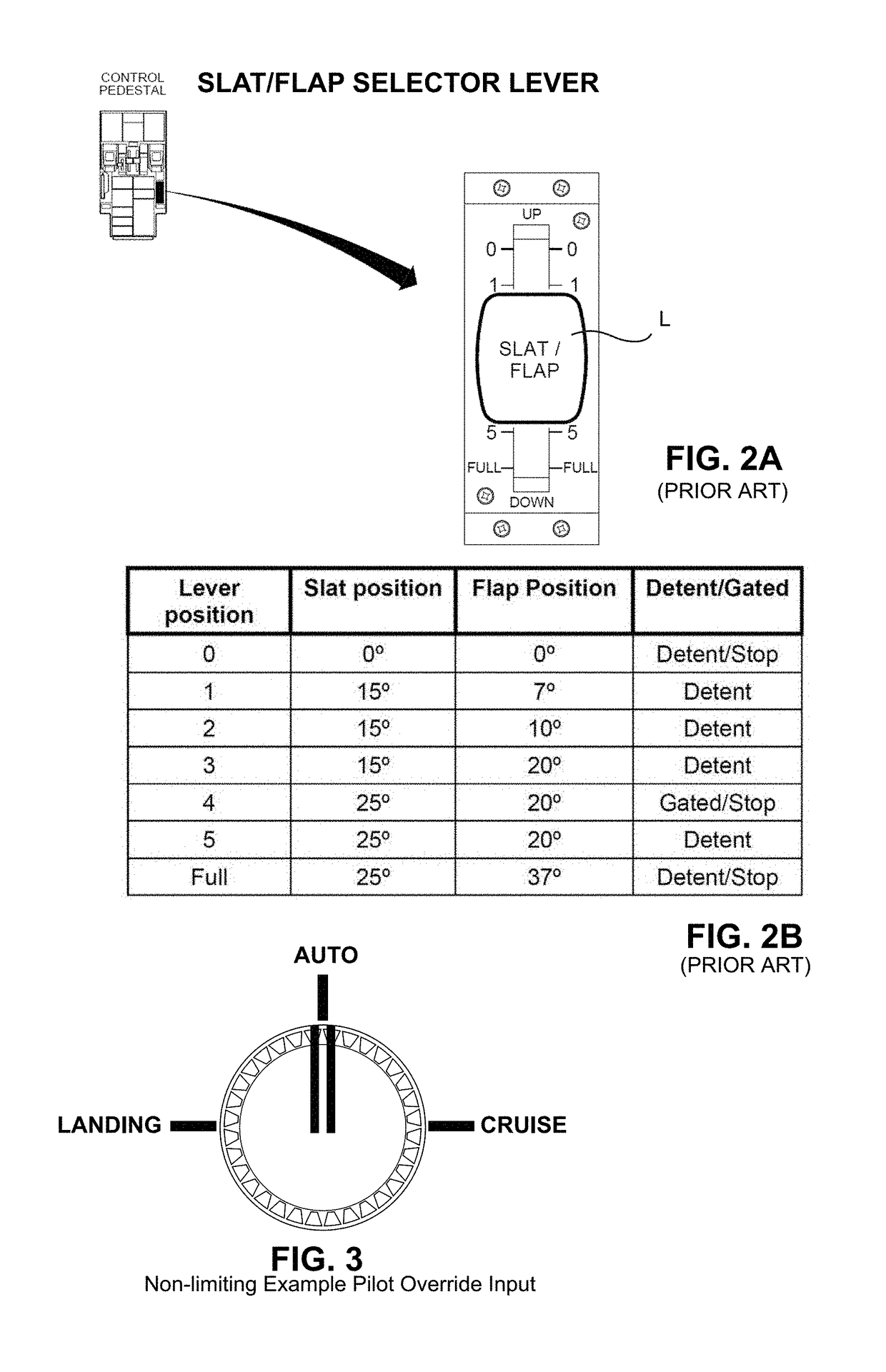
[0044]FIG. 3 presents a non-limiting example of an improved slat / flap selector lever or control, wherein the lift control device position selecting mechanism has exactly and only 3 states: Auto, Flap Full and Flap Up (or Auto, Flap Configuration for Cruising, and Flap Configuration for Landing). In the Auto state, the lift control device positioning process becomes automatic. In fact, FIG. 3 shows a non-limiting example. In a possible implementation, the positions would be FULL and UP, but the idea is to have a position for cruise and a position for landing. Some airplanes have negative flaps for cruise configuration (instead of flaps 0), and, depending on the failure hazard analysis of a specific design, the best flap may not be the FULL.

[0045]Dur...


PUM


Abstract

Aircraft and associated methods, apparatus, system and storage devices for automatically positioning of lift control devices such as high lift devices including slats and flaps so an aircraft equipped with this technology will not need to count on the crew to command the lift control devices.

Description

CROSS-REFERENCE TO RELATED APPLICATIONS[0001]None.STATEMENT REGARDING FEDERALLY SPONSORED RESEARCH OR DEVELOPMENT[0002]None.FIELD[0003]The technology herein relates to aeronautics and flight control, and more particularly to aircraft and associated methods, apparatus, system and storage devices for automatically positioning lift control devices so an aircraft equipped with this technology will not need to count on the crew to command the lift control devices.BACKGROUND AND SUMMARY[0004]During the operation of an airplane, the pilots have the responsibility to decide when to command the lift control devices in order to guarantee performance targets and operational requirements. These decisions are often taken during periods of intense workload, when errors are more likely to occur. An inadequate command at the wrong time could potentially cause degradation of safety margins, exceedance of structural limits, or an aerodynamic stall. The parameters and limits that the pilot uses to sup...

Claims


Application Information

Patent Timeline
Patent Type & Authority Applications(United States)
IPC IPC(8): G05D1/00B64C9/16B64C9/22B64C3/58B64D31/00B64D43/00
CPCG05D1/0088B64C9/16B64C9/22B64C3/58B64D31/00B64D43/00B64C13/00B64C13/02B64C13/16G05D1/101B64C13/18B64C13/22G05D1/042
Inventor TURETTA, PAULO EMILIO DA SILVAFERREIRA, DANIEL PAULO DE TARSORODRIGUES, IGOR MIRANDA
Owner EMBRAER SA
Why Eureka
Try Eureka