Circular tube conveyor material flow control device

A control device and conveyor technology, applied in the directions of transportation and packaging, loading/unloading, etc., can solve problems such as initiation accidents, pipe bursts on round pipe belt conveyors, uneven layout, etc.

Active Publication Date: 2016-11-09
NORTHERN HEAVY IND GRP CO LTD
View PDF5 Cites 1 Cited by
  • Summary
  • Abstract
  • Description
  • Claims
  • Application Information

AI Technical Summary

Problems solved by technology

However, the circular pipe belt conveyor has relatively high requirements on the filling rate of materials. The filling rate generally referred to is a theoretical value calculated based on the transport volume, belt speed, and pipe diameter. In actual operation, some incoming material conveying equipment is often not accurate. The control of the material flow makes the material not evenly arranged on the conveyor bel

Method used


Image

  • Circular tube conveyor material flow control device
  • Circular tube conveyor material flow control device

Examples


Embodiment Construction

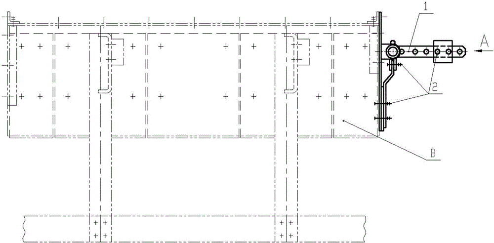
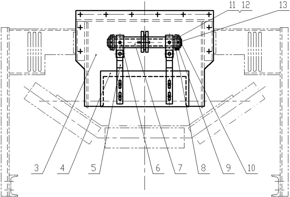
[0011] Referring to the accompanying drawings, a material flow control device for a round pipe conveyor includes an anti-tension counterweight device 1, a fastener 2, a baffle plate 3, an adjustment plate 4, an adjustment link plate 5, a joint ring 6, a shaft 7, and a fixed plate 8. Fixed ring 9, sealing plate 10, pin shaft 11, first cotter pin 12, second cotter pin 13, the material flow control device of the circular tube conveyor is installed at the front end of the material guide trough B, instead of the material guide The front curtain of groove B, the baffle plate 3 is made of 6mm thick steel plate, the upper three sides are flange-connected with the outlet of the front section of the material guide groove B, and the lower part has a rectangular opening, and the outside of the rectangular opening of the baffle plate 3 is covered by the adjustment plate 4 components. Fasteners 2 are used to connect the plate 4 and the adjusting connecting plate 5, the anti-tension counterwe...


PUM


Abstract

A circular tube conveyor material flow control device comprises a pre-tensioning counterweight device, a fastener, a baffle, an adjusting plate, an adjusting linkage plate, a joint ring, a shaft, a fixing plate, a fixing ring, a sealing plate, a pin shaft, a first cotter pin and a second cotter pin. The circular tube conveyor material flow control device is installed at the end of a front section of a material guiding groove B to replace a front curtain of the material guiding groove B. The baffle is made of a steel plate with the thickness being 6 mm. The three faces of the upper portion are connected with an outlet of the front section of the material guiding groove B through a flange, a rectangular opening is formed in the lower portion of the baffle. The outer side of the rectangular opening of the baffle is covered with an adjusting plate assembly. The adjusting plate and the adjusting linkage plate are connected through a fastener. The pre-tensioning counterweight device is connected with the shaft. The adjusting linkage plate is connected with the shaft through the joint ring, the pin shaft and the first cotter pin. The shaft is connected to the baffle through the fixing plate. The two ends of the shaft are sealed and welded through sealing plates. The device can effectively control material flow, the materials can uniformly enter a circular tube, the filling rate is close to a theoretical filling rate, explosion of a circular tube conveyor is avoided, and the device is applied to the field of bulk material conveying devices.

Description

technical field [0001] The invention relates to a material flow control device for a circular pipe conveyor in the field of bulk material conveying equipment. Background technique [0002] At present, the circular pipe belt conveyor has been widely used in GCO railway and port infrastructure projects. The general circular pipe belt conveyor has a bandwidth of 1300mm, a belt speed of 3.5m / s, a transport capacity of 2000t / h, and a pipe diameter of 350mm. The round pipe belt conveyor has the characteristics of good environmental protection and energy saving, large conveying capacity, flexible arrangement of the conveying line along the space curve, and closed transportation. However, the circular pipe belt conveyor has relatively high requirements on the filling rate of materials. The filling rate generally referred to is a theoretical value calculated based on the transport volume, belt speed, and pipe diameter. In actual operation, some incoming material conveying equipment i...

Claims


Application Information

Patent Timeline
IPC IPC(8): B65G69/04
CPCB65G69/04
Inventor 张宏敏李杰王洋付瑶陈晓光敫旭东刘俊明谢添任双喜范丽路军
Owner NORTHERN HEAVY IND GRP CO LTD
Why Eureka
Try Eureka