
Mechanical drive two-way self-locking device

A mechanical transmission, two-way self-locking technology, applied in the direction of the hoisting device, the spring mechanism, etc., can solve the problems of safety accidents, difficult to control, fluctuations in the descending speed of heavy objects, etc., to improve the safety factor, simple structure, and free operation. Effect

Inactive Publication Date: 2016-11-09
HENAN POLYTECHNIC INST
View PDF7 Cites 9 Cited by
  • Summary
  • Abstract
  • Description
  • Claims
  • Application Information

AI Technical Summary

Problems solved by technology

In this case, it is difficult to control the magnitude of the imbalance between the lifting force and the gravity of the object. It is inevitable that there will be fluctuations in the falling speed of the heavy object, which will also cause the gravity to fluctuate, thus greatly increasing the difficulty of operation for operators. , and even cause the operation to be out of control, and the heavy object will fall rapidly, causing a safety accident
This problem has not yet been satisfactorily resolved

Method used


Image

  • Mechanical drive two-way self-locking device
  • Mechanical drive two-way self-locking device

Examples


Embodiment 1

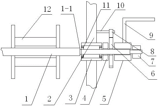
[0020] Such as figure 1 As shown, the mechanical transmission two-way self-locking device of the present invention includes a support frame body 2, a transmission shaft 1, a ratchet 6 and a pawl 8 installed on the support frame body 2, and the pawl 8 can be installed on the support frame body through a rotating shaft 10 2, the pawl 8 is engaged with the ratchet 6 to realize the braking of the ratchet 6. The transmission shaft 1 is connected to the support frame body 2 through the seat cover 3, and the seat cover 3 can be a casing structure welded to the support frame body 2; Thrust bearing 11 is worn and connected with bearing seat, and it is more portable and flexible to operate. The ratchet 6 is movably connected with the transmission shaft 1 and can rotate freely on the transmission shaft 1. The transmission shaft 1 is provided with a limiting structure 1-1 and a friction assembly, wherein the limiting structure 1-1 is arranged on the load side of the seat cover 3 to prev...

Embodiment 2

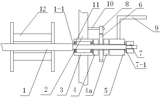
[0023] see figure 2 , as a further improvement, in the mechanical transmission two-way self-locking device of this embodiment, the number of the friction damping parts is 2, and the two friction damping parts 4, 4a are respectively arranged on both sides of the ratchet, which can increase Self-locking torque, using friction damping parts 4 and 4a with an outer diameter of 60mm, the maximum self-locking torque can reach more than 1000kg. When it is necessary to increase the load torque, just increase the effective cross-sectional area of ​​friction damping parts 4 and 4a appropriately. . The actuating screw sleeve 5 can be connected with the transmission shaft 1 through multiple threads, which is convenient to increase the lead of the connecting thread, increase the transmission of the rotational torque of the actuating screw sleeve 5, and make the reverse rotation operation more sensitive. The compression nut 7 is preferably connected to the transmission shaft 1 through a fi...


PUM

PropertyMeasurementUnit
Outer diameteraaaaaaaaaa

Abstract

The invention discloses a mechanical drive two-way self-locking device, which comprises a support bracket body, a drive shaft, a ratchet wheel and a pawl arranged on the support bracket body. The drive shaft is connected with the support bracket body through a seat cover; the ratchet wheel is movably connected with the drive shaft; and a limited structure and a friction assembly are arranged on the drive shaft. The friction assembly comprises operation threaded sleeves, compression nuts and friction damping parts. The mechanical drive two-way self-locking device provided by the invention adopts a ratchet wheel-friction self-locking structure, so that not only can the favorable anticlockwise self-locking be ensured, but also the clockwise rotation self-locking can be realized, the anticlockwise rotation operation can be applied under the state of anticlockwise self-locking, the rotation at any direction and the self-locking and unlocking at any position can be realized only through the operation control of an operation mechanism, special unlocking operation is not needed, and the operation is random, convenient and fast.

Description

technical field [0001] The invention relates to the technical field of mechanical transmission, in particular to a two-way self-locking device for mechanical transmission. Background technique [0002] Mechanical transmission self-locking devices are widely used, and the self-locking mechanism composed of ratchet and pawl is the most widely used, mainly used in mechanical equipment and lifting equipment, etc. The ratchet mechanism is often used in manual winches to prevent reversal. At present, the ratchet self-locking mechanism in the lifting equipment is mostly composed of a ratchet fixed on the main shaft of the winch and a pawl mounted on the rocker, so as to realize one-way braking or intermittent in the lifting process of heavy objects. And when the weight needs to be lowered slightly or slowly, it is often necessary to pre-apply force in the lifting direction of the heavy object first, so that the pawl is separated from the ratchet teeth of the ratchet, and then the p...

Claims


Application Information

Patent Timeline
IPC IPC(8): B66D1/54B66D1/28
CPCB66D1/54B66D1/28
Inventor 李晓静胡龙廷张成光熊毅王蕾周炜明李晓东余东满
Owner HENAN POLYTECHNIC INST
Learn More