Preparation method for optical fiber preform rod

A technology of optical fiber preform and manufacturing method, which is applied in the field of optical fiber manufacturing, can solve the problems of excessive cut-off wavelength and zero-dispersion wavelength of optical fiber, and achieve the effect of reducing the fluctuation of core-clad ratio and avoiding the excessive cut-off wavelength and zero-dispersion wavelength

Active Publication Date: 2016-11-09
ZHEJIANG FUTONG OPTICAL FIBER TECH +1
View PDF3 Cites 1 Cited by
  • Summary
  • Abstract
  • Description
  • Claims
  • Application Information

AI Technical Summary

Problems solved by technology

[0004] However, the above-mentioned deposition process is for the outer cladding deposition at the same time for core rods with different optical parameters, that is, regardless of the t / a (outer diameter to core diameter ratio) and refractive index difference (delta) of the core rod. value, the deposition time is 8 hours, which leads to the D between different preforms 3 / D 1 If the fluctuation range is large, then the refractive index difference (delta) fluctuates greatly, and the cutoff wavelength is related to the refractive index difference, which leads to the problem that the fiber cutoff wavelength and zero dispersion wavelength exceed the standard

Method used


Image

  • Preparation method for optical fiber preform rod
  • Preparation method for optical fiber preform rod

Examples


Embodiment Construction
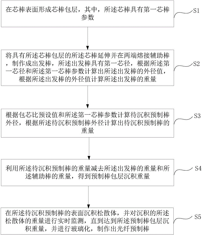
[0034] The core idea of ​​the present invention is to provide a method for manufacturing an optical fiber preform, which can reduce the fluctuation of the core-cladding ratio of the preform and avoid the problem that the cut-off wavelength and zero dispersion wavelength of the optical fiber exceed the standard.

[0035] The following will clearly and completely describe the technical solutions in the embodiments of the present invention with reference to the accompanying drawings in the embodiments of the present invention. Obviously, the described embodiments are only some, not all, embodiments of the present invention. Based on the embodiments of the present invention, all other embodiments obtained by persons of ordinary skill in the art without making creative efforts belong to the protection scope of the present invention.

[0036] The first optical fiber preform manufacturing method provided by the embodiment of the present application is as follows: figure 1 as shown, ...


PUM


Abstract

The invention discloses a preparation method for an optical fiber preform rod. The preparation method comprises the steps: forming a core rod coating on the surface of a core rod, wherein the core rod has first core rod parameters; extending the core rod, fusing auxiliary rods to the two ends of the core rod so as to prepare a start rod which has a first core diameter, calculating an outside diameter value of the start rod, and calculating the weight of the start rod according to the outside diameter value of the start rod; calculating outside diameter of the preform rod to be deposited, and calculating the weight of the preform rod to be deposited according to the outside diameter of the preform rod to be deposited; obtaining the weight of the deposited coating of the preform rod; and depositing loose bodies to the surface of the preform rod to be deposited, carrying out real-time monitoring on the weight of the deposited loose bodies until the weight reaches the weight of the deposited coating of the preform rod, and carrying out vitrification, thereby preparing the optical fiber preform rod. According to the preparation method for the optical fiber preform rod, the fluctuation of core coating ratio of the preform rod can be lowered, and the problem that fiber cutoff wavelength and zero dispersion wavelength are overproof is solved.

Description

technical field [0001] The invention belongs to the technical field of optical fiber manufacturing, and in particular relates to a method for manufacturing an optical fiber preform rod. Background technique [0002] The optical fiber preform is the core raw material for manufacturing optical fibers. The optical fiber preform adopts VAD (axial vapor deposition method) to make the core rod and part of the cladding. After vitrification, the core rod is extended to a starting rod (target rod) with a certain outer diameter. Then use OVD (outside vapor deposition method) to deposit a large amount of cladding on the outside of the target rod, and vitrify the cladding and target rod together to become an optical fiber preform. 125um bare fiber. [0003] In the existing optical fiber prefabricated rod process, the core rod loose body is first deposited by VAD method, and the core rod is formed after vitrification. , this whole composition is called the target rod of prefabricated r...

Claims


Application Information

Patent Timeline
Patent Type & Authority Applications(China)
IPC IPC(8): C03B37/018
CPCC03B37/018
Inventor 马静杨军勇冯高锋章海峰陈坚盾
Owner ZHEJIANG FUTONG OPTICAL FIBER TECH
Why Eureka
Try Eureka