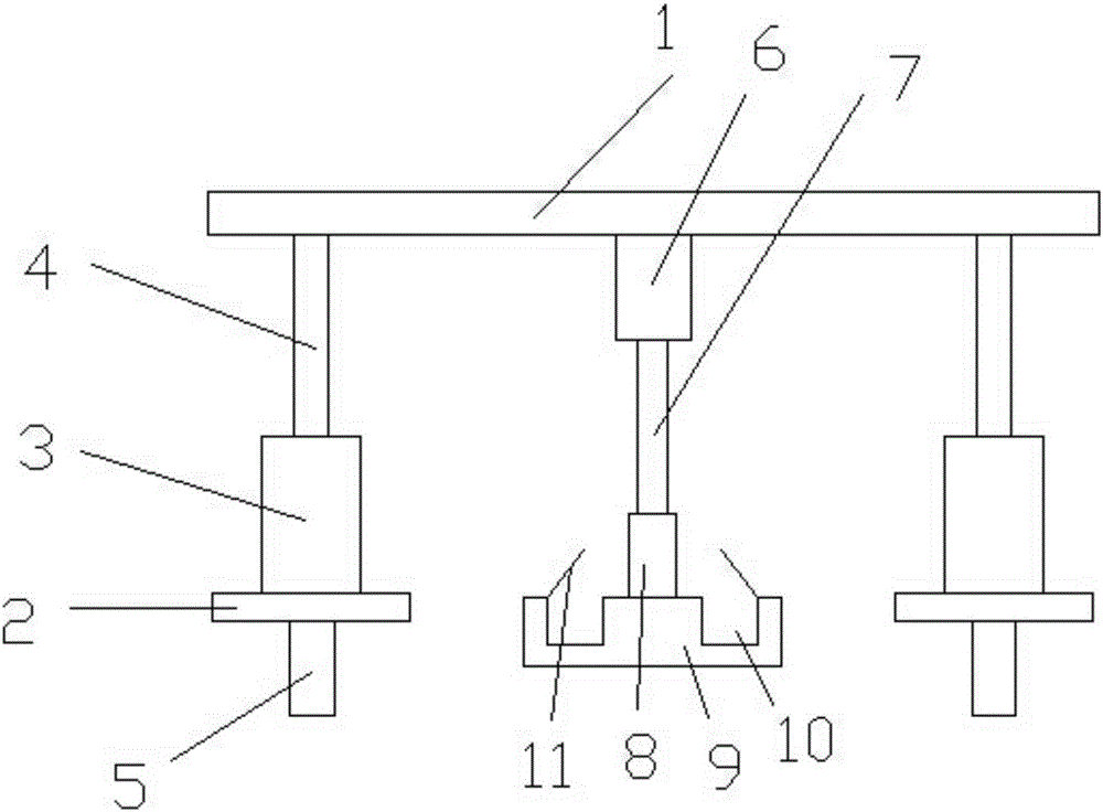
Tamping device for construction

A technology of hydraulic telescopic rod and hydraulic device, which is used in infrastructure engineering, soil protection, construction, etc., can solve problems such as poor flexibility and unadjustable tamping weight, and achieve a high degree of automation, good tamping effect, and good flexibility. Effect

Inactive Publication Date: 2016-11-09
WUXI LEHUA AUTOMATION TECH
View PDF8 Cites 0 Cited by
  • Summary
  • Abstract
  • Description
  • Claims
  • Application Information

AI Technical Summary

Problems solved by technology

[0010] 3. The tamping machine shall not be rammed on frozen soil, solid stone, broken brick and stone mixed soil. When the tamping machine turns, it shall not turn sharply and let it walk freely without support. No one is allowed inside. When multiple rammers are ramming, the left-right distance shall not be less than 5m, and the front-to-back distance shall not be less than 10m. Operators must wear insulated shoes and insulated gloves
However, this kind of tamping and compacting device has poor flexibility, and the tamping weight cannot be adjusted.

Method used


Image

  • Tamping device for construction

Examples


Embodiment Construction

[0038] figure 1 The shown construction tamping device includes a support rod, two support plates are arranged symmetrically under the support rod, each support plate is provided with a first hydraulic device, the lower end of each support plate is connected to a roller, and the upper end of the first hydraulic device is connected to the second A hydraulic telescopic rod, the first hydraulic telescopic rod is slidably connected to the support plate, a second hydraulic device is provided between the two first hydraulic telescopic rods, the second hydraulic device is slidably connected to the support rod, and the lower part of the second hydraulic device is connected The second hydraulic telescopic rod, the lower part of the second hydraulic telescopic rod is detachably connected to the pressure block through the bushing, several grooves are symmetrically arranged on the pressure block, and the opening of the groove is connected with an openable cover plate.

[0039] Described ro...


PUM


Abstract

The invention relates to a tamping device for construction. The tamping device comprises a support rod, two support plates are symmetrically arranged under the support rod, each support plate is provided with a first hydraulic press thereon, a roller is connected to the lower end of each support plate, a first hydraulic telescopic rod is connected to the upper end of each first hydraulic press, the first hydraulic telescopic rods are slidably connected with the corresponding support plates, a second hydraulic press is arranged between the first hydraulic telescopic rods and is slidably connected with the support rod, a second hydraulic telescopic rod is connected to the lower portion of the second hydraulic press, the lower portion of the second hydraulic telescopic rod is detachably connected with a pressure block through a shaft sleeve, a plurality of grooves are symmetrically arranged on the pressure block, and cover plates capable of opening are connected to positions of openings of the grooves. The tamping device is high in degree of automation and good in flexibility, and pressure in tamping can be adjusted according to tamping requirements.

Description

technical field [0001] The invention relates to a ramming device, in particular to a construction ramming device. Background technique [0002] A rammer refers to a machine used for compaction. It is mostly used for leveling and compacting the foundation during construction. [0003] The rammer is divided into fire rammer, electric frog rammer and fast impact rammer according to the type. [0004] Fire rammer: It is made according to the principle of a two-stroke internal combustion engine. There are upper and lower pistons in the cylinder, the upper piston is an internal combustion piston, and the lower piston is a buffer piston. The lower part of the cylinder is equipped with a rammer with an inclined bottom surface, so that the vertical axis of the cylinder is deflected forward. The upper piston rod protrudes from the through hole in the middle of the cylinder top cover, the lower piston rod protrudes from the lower end of the cylinder, and is integrated with the tampe...

Claims


Application Information

Patent Timeline
Patent Type & Authority Applications(China)
IPC IPC(8): E02D3/046
CPCE02D3/046
Inventor 钱国东
Owner WUXI LEHUA AUTOMATION TECH
Why Eureka
Try Eureka