Telegraph pole installation robot

A robot and utility pole technology, applied in the field of electric power grid, can solve the problem of occupying resources and other costs, and achieve the effects of saving manpower, reducing risks, and improving construction efficiency

Active Publication Date: 2016-11-09
浙江邮电职业技术学院 +1
4 Cites 30 Cited by

AI-Extracted Technical Summary

Problems solved by technology

[0002] Buried electric poles are an essential project in the construction of electric power infrastructure. This process requires the use of a lot of me...

Abstract

The invention provides a telegraph pole installation robot. The telegraph pole installation robot comprises a walking mechanism, a rotary table, two bottom plates, a punching module and a poling module, and is characterized in that the rotary table is slidingly installed above a slide rail located above the walking mechanism; the two bottom plates are hinged to a platform; the punching module is slidingly installed on a linear guide rail of one bottom plate; the poling module is slidingly installed on a linear guide rail of the other bottom plate. The telegraph pole installation robot can be used for automatically digging a pole pit and automatically poling, so that manpower is saved; the equipment is simple, the construction efficiency is improved and the dangerousness of working is reduced.

Application Domain

Technology Topic

Image

  • Telegraph pole installation robot
  • Telegraph pole installation robot
  • Telegraph pole installation robot

Examples

  • Experimental program(1)

Example Embodiment

[0020] The technical solutions of the present invention will be further described in detail below through embodiments and in conjunction with the accompanying drawings.
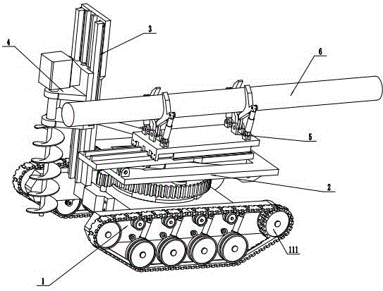
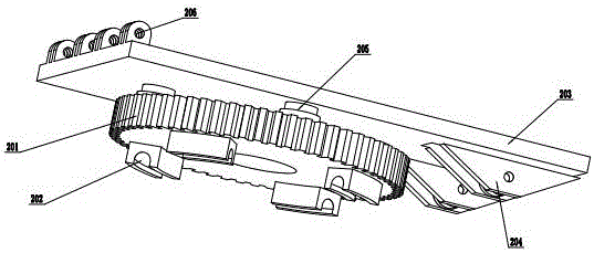
[0021] like figure 1 , figure 2 , image 3 , Figure 4 , Figure 5 , Image 6 , Figure 7 As shown, a utility pole installation robot includes a traveling mechanism 1, a turntable 2, two bottom plates 3, a punching module 4, and a pole module 5, and is characterized in that the turntable 2 is slidably installed on the top of the traveling mechanism 1 above the slide rail 110; the two base plates 3 are hinged on the platform 203; the punching module 4 is slidably installed on the linear guide rail 303 of one base plate 3; the pole module 5 is slidably installed on the other base plate 3 on the linear guide rail 303;
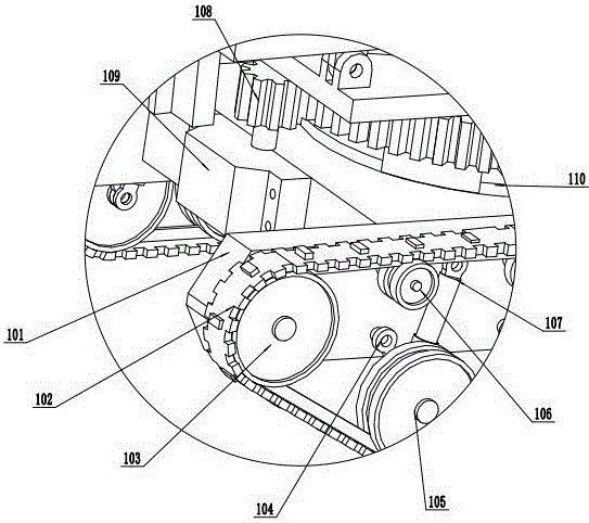
[0022] The walking mechanism 1 includes a base 101, 2 crawlers 102, 2 front guide wheels 103, 8 rocking arms 104, 8 road wheels 105, 8 guide wheels 106, 8 shock absorbers 107, pinions 108, The first hydraulic motor 109, slide rail 110, 2 driving wheels 111, 2 second hydraulic motors 112, the 2 front guide wheels 103 are rotated and installed on the installation shafts on both sides of the base 101; the 8 The guide wheels 106 are rotatably installed on the mounting shafts on both sides of the base 101; the two ends of the eight rocker arms 104 and the eight shock absorbers 107 are respectively hinged on the rotating shafts of the eight road wheels 105 and the installation on both sides of the base 101. shaft; the two second hydraulic motors 112 are fixed on both sides of the base 101; the two driving wheels 111 are fixed on the output shafts of the two second hydraulic motors 112; the two crawlers 102 is installed on 2 front guide wheels 103, 8 road wheels 105, 8 guide wheels 106, and 2 driving wheels 111; a slide rail 110 is provided above the base 101; the first hydraulic motor 109 passes through Bolts are fixedly installed on the mounting holes at the front end of the base 101; the pinion 108 is fixedly installed on the output shaft of the first hydraulic motor 109;
[0023] The turntable 2 includes a large gear 201, four first sliders 202, a platform 203, two support frames 204, four poles 205, and four first brackets 206. The four first sliders 202 is evenly distributed on the lower end surface of the large gear 201 and cooperates with the slide rail 110; the two ends of the four poles 205 are respectively fixedly connected to the upper end surface of the large gear 201 and the lower end surface of the platform 203; The pinion 108 is engaged; the upper end of the platform 203 is provided with four first brackets 206; the lower end of the platform 203 is provided with two support frames 204;
[0024] The base plate 3 includes a base plate seat 301, a first hydraulic cylinder 302, two linear guide rails 303, a second bracket 304, two third brackets 305, and two second hydraulic cylinders 306. The two linear guide rails 303 is fixedly installed on the upper end surface of the floor seat 301; the lower end surface of the floor seat 301 is provided with two third supports 305 and the second support 304; the two second hydraulic cylinders 306 are fixedly installed on the upper end surface of the floor seat 301 The two third brackets 305 are hinged on the two first brackets 206 through pin shafts; one end of the first hydraulic cylinder 302 is hinged on the support frame 204, and the other end is hinged on the second bracket 304;
[0025] The punching module 4 includes a punching base 401, two second sliders 402, a screw 403, and a third hydraulic motor 404, and the lower end of the punching base 401 is provided with two second sliders 402, the two second sliders 402 cooperate with the two linear guide rails 303; the third hydraulic motor 404 is fixedly installed on the fixed frame on the upper end surface of the punching base 401; the screw rod 403 is fixedly installed On the output shaft of the third hydraulic motor 404; the perforated base 401 is fixedly installed on the flanges at the ends of the two second hydraulic cylinders 306 through the lower fixing seat;
[0026] The pole module 5 includes a pole base 501, two third sliders 502, four third hydraulic cylinders 503, and four claws 504. The lower end of the pole base 501 is provided with 2 A third slider 502, the two third sliders 502 cooperate with the two linear guide rails 303; the four claws 504 are hinged in groups of two on the hinge bracket on the upper end surface of the pole base 501 One end of the four third hydraulic cylinders 503 is hinged on the hinge bracket on the upper end surface of the pole base 501, and the other end is hinged on the bracket on the four claws 504;
[0027] The hydraulic cylinders and hydraulic motors are respectively connected to the hydraulic pump station inside the base 101 through oil pipes.
[0028] The above descriptions are only preferred embodiments of the present invention, and are not intended to limit the present invention. For those skilled in the art, the present invention may have various modifications and changes. Any modifications, equivalent replacements, improvements, etc. made within the spirit and principles of the present invention shall be included within the protection scope of the present invention.
[0029]The working principle of the present invention is as follows: first, set the position where the pole is required, place the electric pole 6 on the pole module 5, extend the third hydraulic cylinder 503 so that the claw 504 clamps the electric pole 6, and pass two second The hydraulic motor 112 drives the crawler belt 102 to rotate, so that the robot moves to a designated position, and the first hydraulic motor 109 drives the small gear 108 to rotate, which drives the large gear 201 to rotate, so that the turntable 2 is offset by a certain angle, and the first hydraulic cylinder 302 is extended to make The punching module 4 stands up, the third hydraulic motor 404 drives the screw 403 to rotate, the second hydraulic cylinder 306 stretches and pushes the punching module 4 to feed downward, and the screw 403 rotates to complete the punching, and the second hydraulic cylinder 306 shrinks and punches The module 4 is retracted, the first hydraulic cylinder 302 shrinks to make the punching module 4 flat, the first hydraulic motor 109 rotates in the opposite direction, and the pole module 5 is offset by the same angle in the opposite direction, and the first hydraulic cylinder 302 is extended to make the pole module 5 stand up, the second hydraulic cylinder 306 extends and pushes the pole module 5 to feed downward, when the pole 6 reaches the bottom of the pit, the third hydraulic cylinder 503 contracts to make the claw 504 release the pole 6, and the second hydraulic cylinder 306 contracts The pole module 5 is retracted, and the two second hydraulic motors 112 drive the crawler belt 102 to rotate, so that the robot moves backward, and the first hydraulic cylinder 302 shrinks to make the pole module 5 flat, and the work is completed.
[0030] In the description of the present invention, it should be noted that the orientation or positional relationship indicated by the terms "up", "down", "front", "rear", "left", "right" etc. are based on the Orientation or positional relationship, or the orientation or positional relationship that the inventive product is usually placed in use, is only for the convenience of describing the present invention and simplifying the description, rather than indicating or implying that the device or element referred to must have a specific orientation, so as to Specific orientation configurations and operations, therefore, are not to be construed as limitations on the invention. Furthermore, the terms "first", "second", "third", etc. are only used to differentiate the description and should not be construed as indicating or implying relative importance.

PUM

no PUM

Description & Claims & Application Information

We can also present the details of the Description, Claims and Application information to help users get a comprehensive understanding of the technical details of the patent, such as background art, summary of invention, brief description of drawings, description of embodiments, and other original content. On the other hand, users can also determine the specific scope of protection of the technology through the list of claims; as well as understand the changes in the life cycle of the technology with the presentation of the patent timeline. Login to view more.

Similar technology patents

All-intelligent chef robot

Owner:BEIJING ROC THEURGY TECH

Classification and recommendation of technical efficacy words

  • Save human effort
  • Simple equipment
Why Eureka
Try Eureka