Motor clutch handle

A handle and clutch block technology, applied in the field of door handles, can solve the problems of poor safety, damage, high price, etc., and achieve the effect of preventing malicious damage and reducing costs

Inactive Publication Date: 2018-08-07
宁波永发智能安防科技有限公司
View PDF1 Cites 0 Cited by
  • Summary
  • Abstract
  • Description
  • Claims
  • Application Information

AI Technical Summary

Problems solved by technology

[0004] The clutch handle driven by the traditional motor has the following disadvantages: the ordinary motor clutch handle only controls whether the handle can be turned, the door can be opened when the handle is turned, and the door cannot be opened if the handle is not turned
However, when the handle cannot be turned, although the door cannot be opened, the handle will be broken if the force is too large at this time, and there is a risk of being violently damaged. Moreover, this kind of door is only locked by the oblique bolt, which is less safe.
There are also smart locks with idling handles on the market, but their clutch structure and motor are set in the lock structure. This kind of electronic lock motor and clutch structure are set in the smart lock, resulting in a complex internal structure of the tumbler lock with clutch function, and the price is high.

Method used


Image

  • Motor clutch handle
  • Motor clutch handle
  • Motor clutch handle

Examples


Embodiment Construction

[0026] The present invention will be further described in detail below in conjunction with the accompanying drawings and embodiments.

[0027] Such as Figure 1-8 Shown is a preferred embodiment of the present invention.

[0028] A motor clutch handle, including

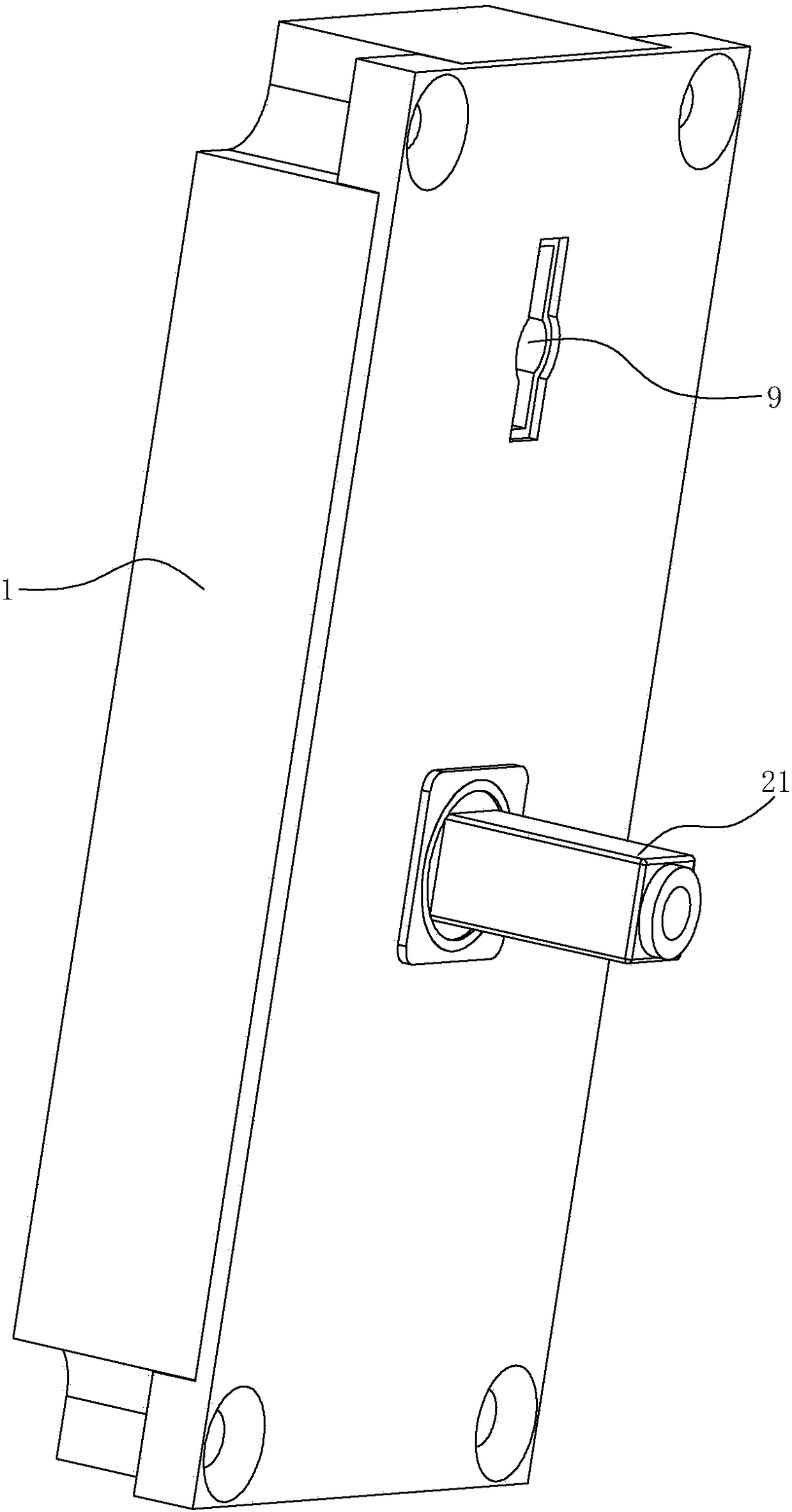
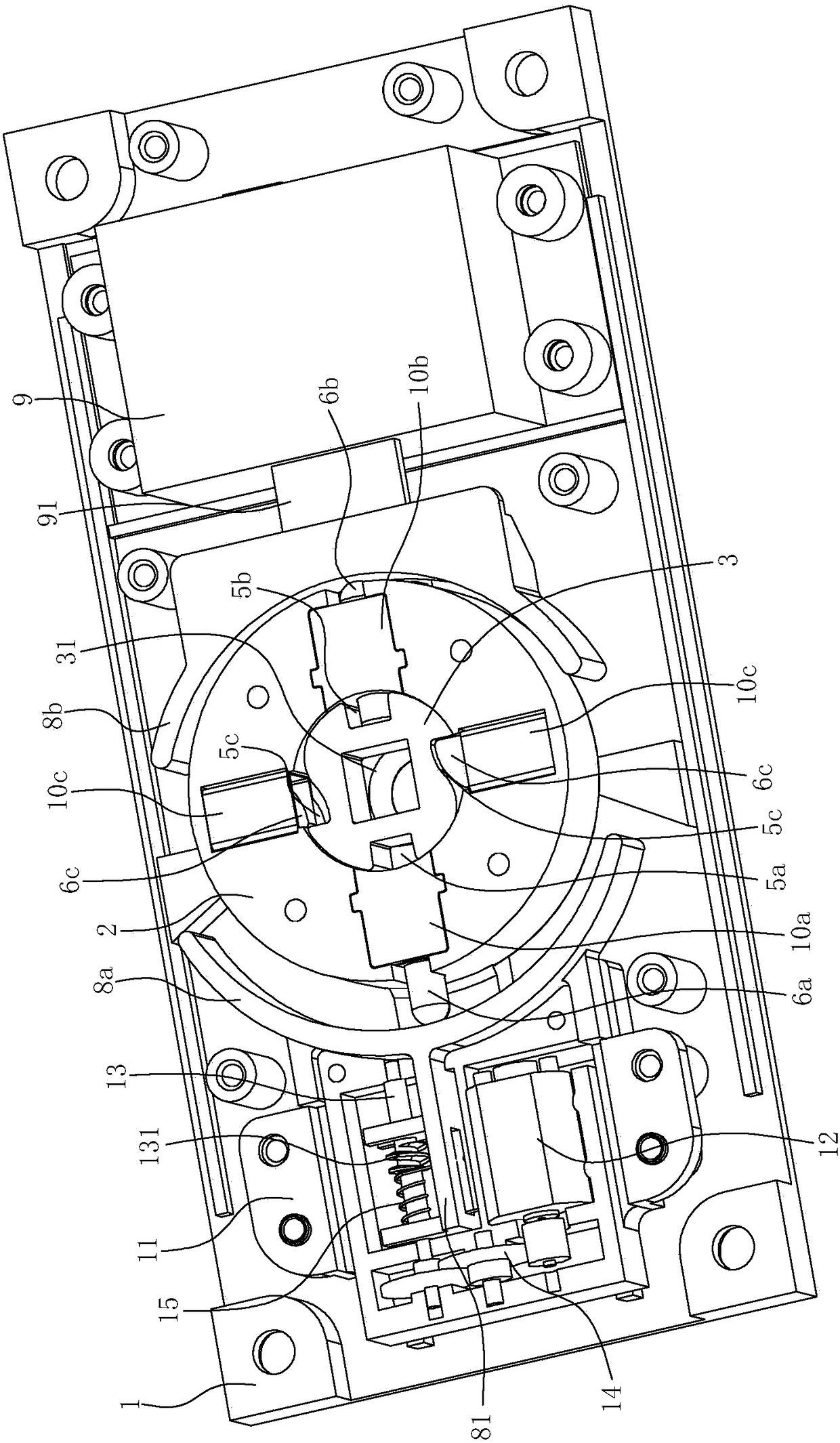
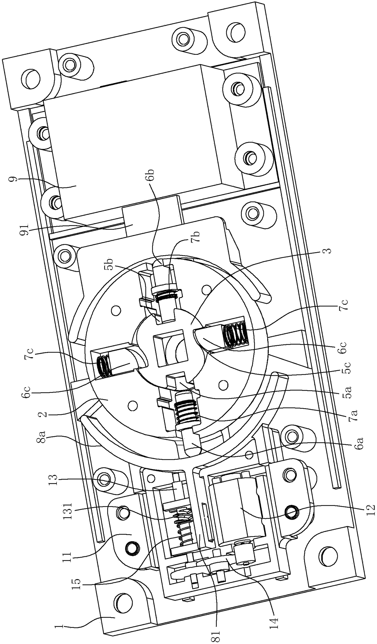
[0029] The shell 1 is composed of a bottom plate and a cover.

[0030] The rotor 2 is installed in the housing 1 for rotation. The rotor 2 has a square shaft 21 for connecting with the outer handle. The square shaft 21 passes through the housing 1 to be connected with the outer handle.

[0031] The torsion spring 4 is arranged in the casing 1 and acts on the rotor 2 to reset the rotor 2 .

[0032] The clutch block 3 is arranged in the concave cavity in the rotor 2 and can rotate relative to the rotor 2. The center of the clutch block 3 has a square hole 31, and the outer periphery of the clutch block 3 has a concave first clutch notch 5a. The rotor 2 is bounded by The first drive pin 6a that can move radially, the ...


PUM


Abstract

The invention relates to a motor separation and reunion handle. The motor separation and reunion handle is characterized in that the handle comprises a shell, a rotor, a torsional spring, a separation and reunion block, a first push piece and a motor driving structure, wherein the rotor is rotatably arranged in the shell, and the torsional spring is arranged in the shell and acts on the rotor to reset the rotor; the separation and reunion block is arranged in a concave cavity in the rotor and can rotate relative to the rotor, a square hole is formed in the center of the separation and reunion block, and a first separation and reunion notch which is inwards concave is formed in the periphery of the separation and reunion block; a first driving pin capable of moving in the radial direction is restrained in the rotor, the outer end of the first driving pin is kept at the tendency of being exposed out of the peripheral face of the rotor under the effect of a first spring, and the inner end of the first driving pin is used for being matched with the first separation and reunion notch; the first push piece is restrained in the shell in a slidable mode, and the first push piece can slide to push the first driving pin to move inwards to be inserted into the first separation and reunion notch; and the motor driving structure is arranged in the shell and used for driving the first push piece to slide. The motor separation and reunion handle can idle when a door is not opened and can be combined with a common lock, so that an intelligent lock function is achieved, and the cost of a whole lock for a room door is greatly lowered.

Description

technical field [0001] The invention relates to a door handle, in particular to a motor clutch handle, which is suitable for use in conjunction with an intelligent lock for a hotel room door. Background technique [0002] The anti-theft door smart lock mainly includes a door handle, a deadbolt and a switch control device. Among them, the door handle can be rotated, including an outer door handle and an inner door handle. The outer door handle and the inner door handle are used to control the switch of the door. The tongue includes several non-automatic retractable dead bolts and an automatic retractable wedge-shaped dead bolt. The switch control device includes a driving device and a transmission device. or the purpose of opening the door. The driving device of the switch control device includes the input terminal of the remote control receiver controlled by the remote control transmitter connected to the positive and negative poles of the DC battery, the output terminals o...

Claims


Application Information

Patent Timeline
Patent Type & Authority Patents(China)
IPC IPC(8): E05B47/06E05B13/00E05B15/00
CPCE05B15/00E05B47/0012E05B47/0692
Inventor 田明曹忠伟
Owner 宁波永发智能安防科技有限公司
Why Eureka
Try Eureka