Small wind turbine blade wing section suitable for low Reynolds number flowing

A wind turbine blade and airfoil technology is applied in the field of small wind turbine blade airfoils, which can solve the problems of low wind energy utilization efficiency of small wind turbines, and achieve the effect of improving the low wind energy utilization efficiency.

Inactive Publication Date: 2016-11-09
XIANGTAN UNIV
View PDF4 Cites 6 Cited by
  • Summary
  • Abstract
  • Description
  • Claims
  • Application Information

AI Technical Summary

Problems solved by technology

[0004] The present invention aims to provide a kind of suitable for Reynolds number6 The flowing airfoil of small wind turbine blades makes it have a higher lift coefficient and a larger lift-to-drag ratio under low Reynolds number flow, which improves the low efficiency of wind energy utilization of small wind turbines

Method used


Image

  • Small wind turbine blade wing section suitable for low Reynolds number flowing
  • Small wind turbine blade wing section suitable for low Reynolds number flowing
  • Small wind turbine blade wing section suitable for low Reynolds number flowing

Examples


Embodiment 1

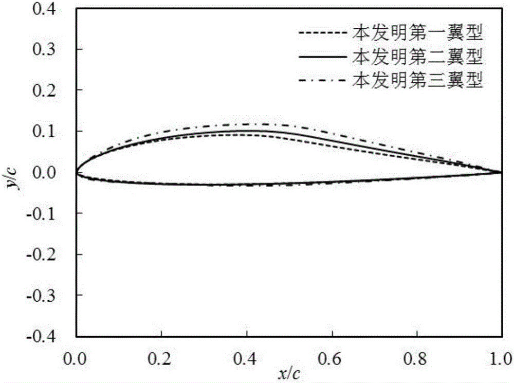
[0020] The maximum thickness of the first airfoil of the present invention is 12% of the chord length, the distance between the maximum thickness point and the leading edge is 35.9% of the chord length, the maximum camber is 3.1% of the chord length, and the distance between the maximum camber point and the leading edge is chord length 36.0% longer.

[0021] The dimensionless two-dimensional coordinates of the upper airfoil and the lower airfoil of the first airfoil of the present invention are respectively shown in Table 1a and Table 1b.

[0022] Table 1a Upper airfoil of the first airfoil

[0023]

[0024]

[0025] Among them, the x / c value indicates the position of a point on the airfoil surface relative to the leading edge in the direction of the chord line, and the y / c value indicates the height from the chord line to a certain point on the airfoil curve.

[0026] Table 1b Lower airfoil of the first airfoil

[0027] serial number

x / c

y / c

seria...

Embodiment 2

[0031] The maximum thickness of the second airfoil of the present invention is 13% of the chord length, the distance between the maximum thickness point and the leading edge is 38.0% of the chord length, the maximum camber is 3.6% of the chord length, and the distance between the maximum camber point and the leading edge is chord length 41.4% longer.

[0032] The dimensionless two-dimensional coordinates of the upper airfoil and the lower airfoil of the second airfoil of the present invention are respectively shown in Table 2a and Table 2b.

[0033] Table 2a Upper airfoil of the second airfoil

[0034] serial number

x / c

y / c

serial number

x / c

y / c

serial number

x / c

y / c

1

0

0

21

0.17491

0.07859

41

0.85931

0.02818

2

0.0001

0.00055

22

0.2092

0.08505

42

0.89353

0.02173

3

0.00024

0.00131

23

0.24335

0.09016

43

0.92402

0.01557

4

0.00044

0.00238...

Embodiment 3

[0041] The cross-section airfoil maximum thickness of the third airfoil of the present invention is 15% of the chord length, the distance between the maximum thickness and the leading edge is 40.7% of the chord length, the maximum camber is 4.3% of the chord length, and the maximum camber and the front edge are 40.7% of the chord length. The edge distance is 44.3% of the chord length.

[0042] The dimensionless two-dimensional coordinates of the upper airfoil and the lower airfoil of the third airfoil of the present invention are respectively shown in Table 3a and Table 3b.

[0043] Table 3a Upper airfoil of the third airfoil

[0044]

[0045]

[0046] Table 3b The lower airfoil of the third airfoil

[0047] serial number

x / c

y / c

serial number

x / c

y / c

serial number

x / c

y / c

1

0

0

21

0.18711

-0.02685

41

0.86671

-0.01055

2

0.00011

-0.0011

22

0.2238

-0.02847

42

0.89913

-0.0...


PUM


Abstract

The invention discloses a small wind turbine blade wing section suitable for low Reynolds number flowing, and belongs to the field of wind turbine blade wing section design. The maximum thickness of the wind turbine blade wing section is 12%-15% of the chord length, the distance between the maximum-thickness position and the front edge is 35.9%-40.7% of the chord length, the maximum camber is 3.1%-4.3% of the chord length, the distance between the maximum-camber position and the front edge is 36.0%-44.3% of the chord length, and the power of a small wind turbine is smaller than or equal to 10 KW. The small wind turbine blade wing section has the higher lift coefficient and the larger lift-drag ratio under the low Reynolds number flowing, the wind energy utilization efficiency of the small wind turbine can be improved, and the small wind turbine blade wing section is more suitable for being applied to small wind turbines in low-wind-speed areas in China.

Description

technical field [0001] The invention belongs to the field of wind turbine blade airfoil design, and specifically relates to an airfoil suitable for Reynolds number<10 6 Flowing small wind turbine blade airfoil, the power of the small wind turbine is ≤10KW. Background technique [0002] With the increasingly prominent international energy issues and the increasing awareness of environmental protection worldwide, the wind power technology industry has developed rapidly, especially the large-scale wind power equipment and marine wind power industries have already achieved a considerable scale of development. The development of small wind turbines is relatively slow, mainly because the aerodynamic design of the blades is relatively weak. [0003] At present, the research on small wind turbine blades in my country is still in its infancy. The small wind turbine blades produced by some manufacturers mainly rely on imitation molding, and there are few independent blade design t...

Claims


Application Information

Patent Timeline
Patent Type & Authority Applications(China)
IPC IPC(8): F03D1/06
CPCF03D1/0641Y02E10/72
Inventor 唐新姿黄轩晴彭锐涛孙松峰
Owner XIANGTAN UNIV
Why Eureka
Try Eureka