Differential lock provided with proximity switch

A technology of proximity switch and head, which is applied in the field of differential lock, can solve the problems of large shape and damage, and achieve the effects of long service life, long operating life and fast response speed

Inactive Publication Date: 2016-11-09
GUANGDONG FUWA HEAVY IND
View PDF8 Cites 0 Cited by
  • Summary
  • Abstract
  • Description
  • Claims
  • Application Information

AI Technical Summary

Problems solved by technology

Because the mechanical pressure switch is limited by the internal structure, its shape is large, and the part protruding from the main reducer assembly after assembly is also long, which makes it easy to be bumped and damaged during assembly, transfer, lifting, packaging and vehicle operation. damage

Method used


Image

  • Differential lock provided with proximity switch
  • Differential lock provided with proximity switch
  • Differential lock provided with proximity switch

Examples


Embodiment Construction

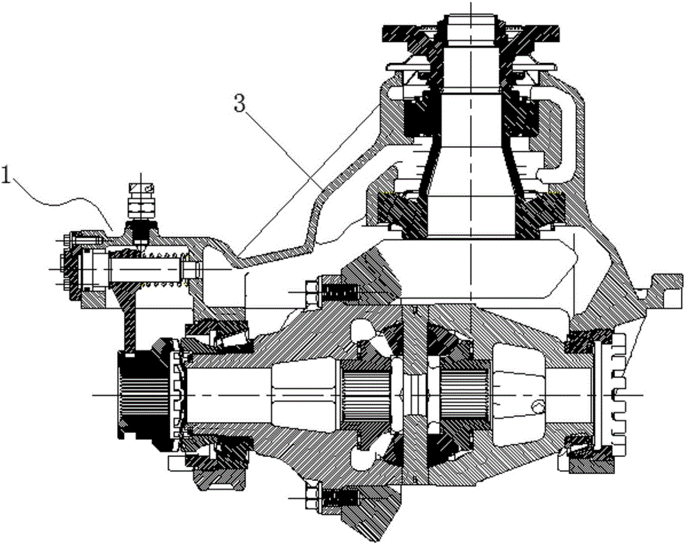
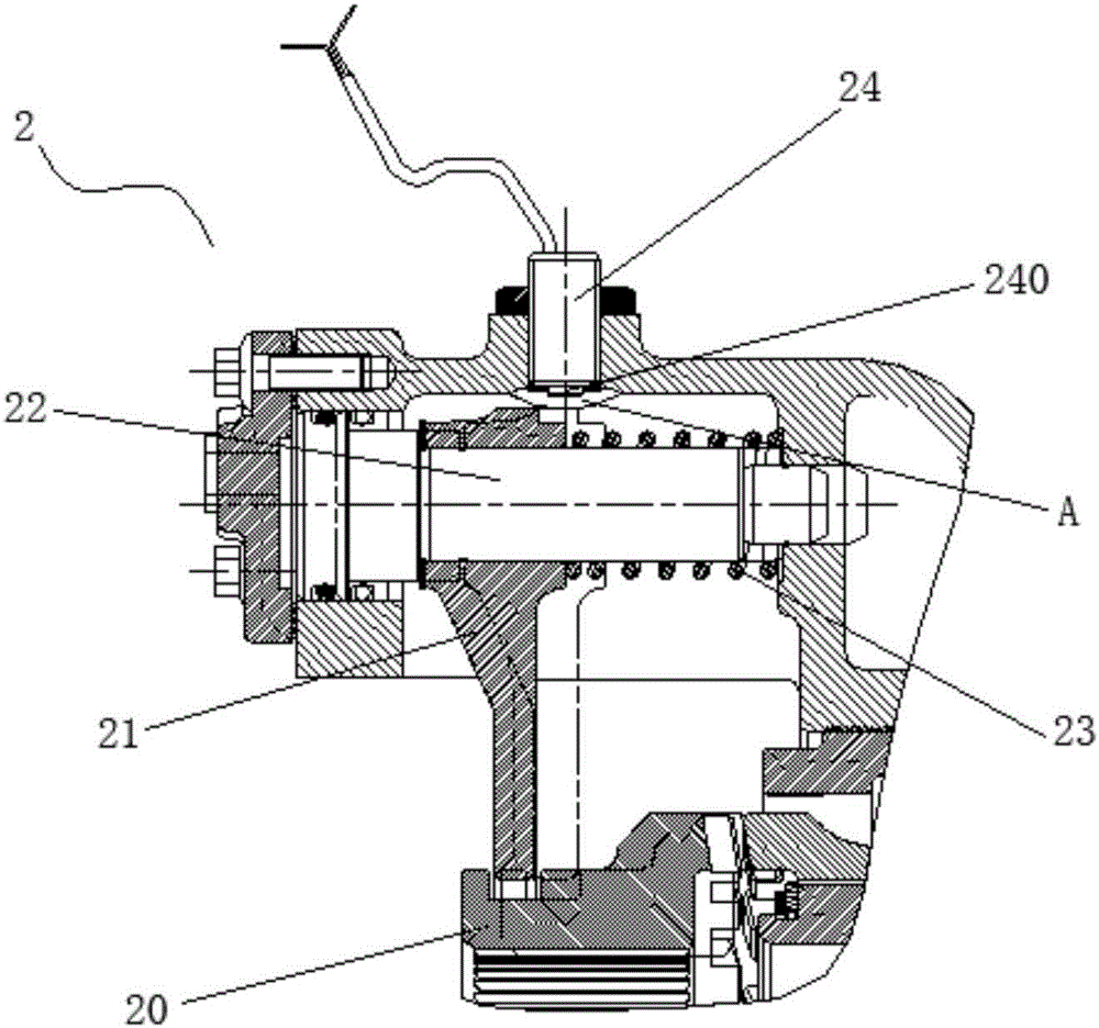
[0022] see image 3 , which is a structural schematic diagram of a differential lock with a proximity switch of the present invention. The differential lock 2 with a proximity switch provided by the present invention includes a sliding joint sleeve 20 , a shift fork 21 , a shift fork shaft 22 movable along its axial direction, a return spring 23 and a proximity switch 24 . image 3 The double dotted line in the middle indicates the position of the shift fork 21 when the differential lock 2 is in the state of locking the differential; the semicircular area indicated by A indicates the detection area of ​​the proximity switch 24 .

[0023] The sliding joint sleeve 20 is provided with an annular groove, the head of the shift fork 21 is fixedly mounted on the shift fork shaft 22 , and its foot is snapped into the annular groove of the sliding joint sleeve 20 . The return spring 23 is sleeved on the shift fork shaft 22, one end thereof abuts against the head of the shift fork 21, ...


PUM


Abstract

The invention discloses a differential lock provided with a proximity switch. The differential lock comprises a sliding combining sleeve, a shifting fork, a shifting fork shaft capable of moving in the axial direction, a reset spring and the proximity switch, wherein the proximity switch is arranged on one side of the head of the shifting fork; when the reset spring is not compressed, the head of the shifting fork is positioned out of a detection area of the proximity switch, and the proximity switch is disconnected; and when the reset spring is compressed, the head of the shifting fork enters the detection area of the proximity switch, and the proximity switch is connected. Compared with the prior art, the proximity switch is adopted to replace a traditional mechanical pressure switch to avoid direct collision and contact, so that the service life is longer; and in addition, the proximity switch is smaller, and the part, stretching out of a main reducer assembly, of the proximity switch after being assembled is also shorter, so that the proximity switch can be effectively prevented from being damaged due to collision during assembling, transporting, hoisting, packaging and finished vehicle operation.

Description

technical field [0001] The invention belongs to the field of auto parts, in particular to a differential lock. Background technique [0002] The differential lock is a locking structure installed on the differential, and its function is to improve the passing ability of the car in muddy, icy and other bad road conditions. When one half shaft of the car is idling, the differential lock can quickly lock the differential, making the two half shafts rigidly connected, so that most of the torque or even all the torque can be transmitted to the non-idling half shaft, fully Use its adhesion to generate enough traction to keep the car moving. [0003] Usually, the differential lock of the heavy-duty drive axle is equipped with a mechanical pressure switch, and the working status of the differential lock is indicated by the on-off of the mechanical pressure switch. see figure 1 , which is a structural schematic diagram of an existing differential lock with a mechanical pressure sw...

Claims


Application Information

Patent Timeline
Patent Type & Authority Applications(China)
IPC IPC(8): F16H48/24F16H48/30
CPCF16H48/24F16H48/30F16H2048/305
Inventor 吴志强吴淑敏张耀李春光郑明陈道斌
Owner GUANGDONG FUWA HEAVY IND
Why Eureka
Try Eureka