Discharge device

A technology of unloading device and unloading valve, which is applied to valve device, lift valve, safety valve, etc., can solve the problems of frequent maintenance, parking, and easy-to-failure systems, and achieve a simple and compact structure, ensure effective reset, and reduce weight. Effect

Inactive Publication Date: 2016-11-09
黄浩华
View PDF3 Cites 1 Cited by
  • Summary
  • Abstract
  • Description
  • Claims
  • Application Information

AI Technical Summary

Problems solved by technology

Most of the existing unloading valves have complex structures (such as electric star unloading valves), and are prone to failure, causing system shutdown, frequent maintenance and other problems

Method used


Image

  • Discharge device
  • Discharge device
  • Discharge device

Examples


Embodiment Construction

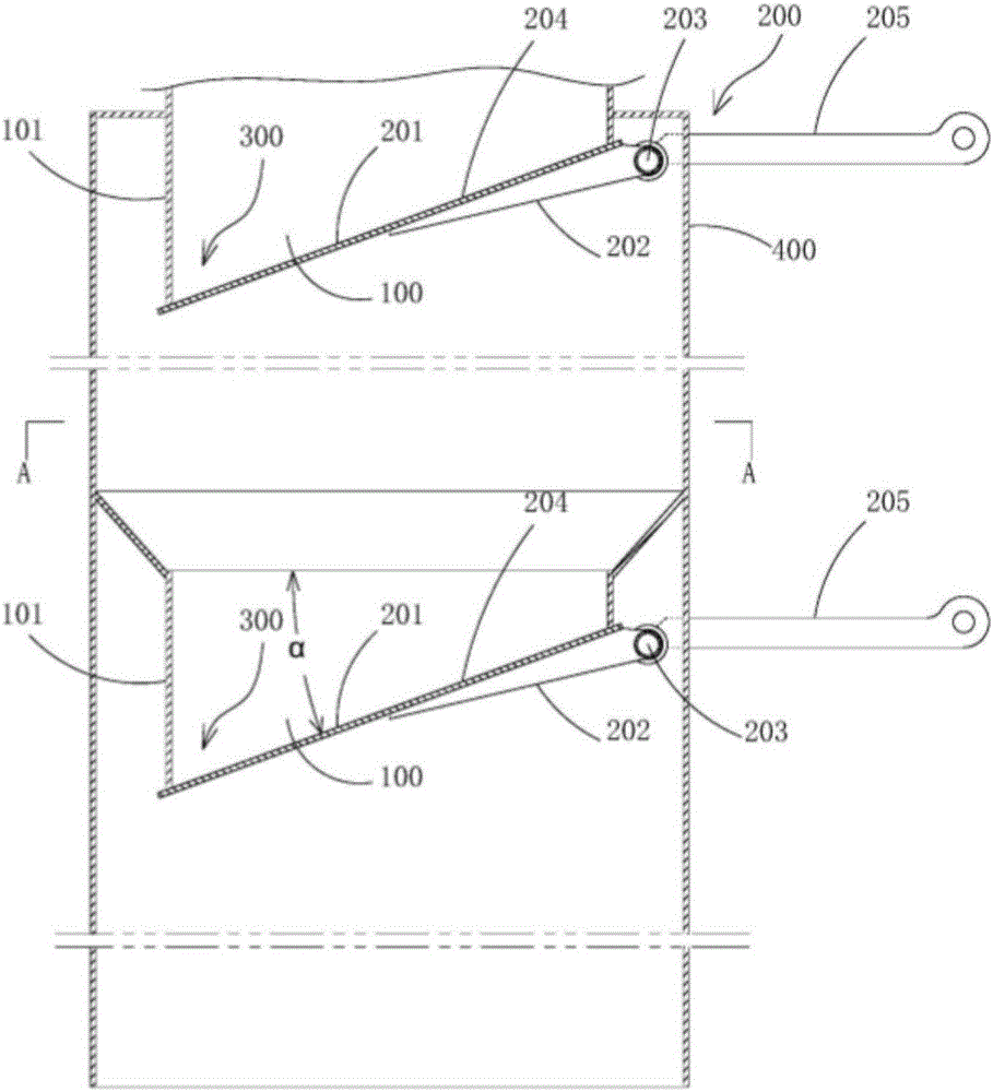
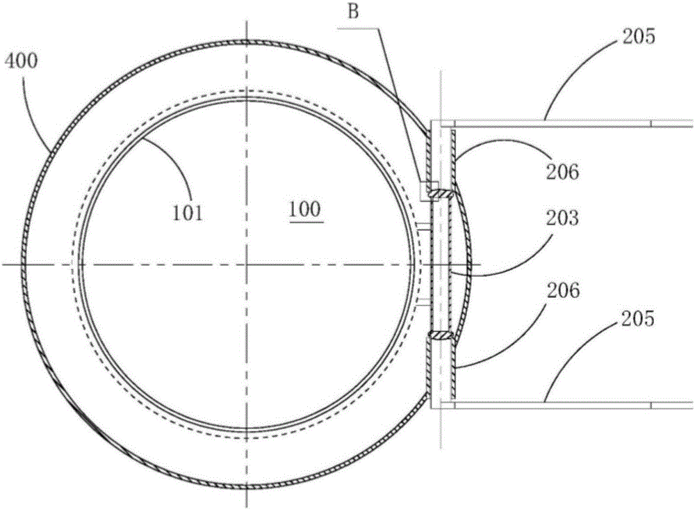
[0010] Such as figure 1 , 2 As shown, the unloading device includes a cylinder 400, and at least one unloading assembly is arranged in the cylinder 400, and the unloading assembly includes an inner tube 101 located in the cylinder 400 and a lower nozzle of the inner tube 101 It is an automatic discharge valve for the discharge valve port 100, the automatic discharge valve includes a beveled discharge valve port 100 and is located below the discharge valve port 100, cooperates with the discharge valve port 100 and is formed by The sealing inclined valve plate 201 held by a set of self-resetting lever mechanism 200, the material accumulation angle 300 is formed between the low end of the sealing inclined valve plate 201 and the side wall of the discharge valve port 100, and the self-resetting lever mechanism has A fulcrum shaft 203 and a force arm 204 and a balance arm 205 connected to the fulcrum shaft 203 and located on both sides of the fulcrum shaft 203 respectively. Adapt...


PUM


Abstract

The invention discloses a discharge device capable of achieving automatic discharge and reset without depending on a power device. The discharge device comprises a barrel. At least one discharge assembly is arranged in the barrel. Each discharge assembly comprises an inner pipe located in the barrel and an automatic discharge valve adopting a lower pipe opening of the inner pipe as a discharge valve opening. Each automatic discharge valve comprises the beveling discharge valve opening and a sealing inclined valve plate which is located below the discharge valve opening, cooperates with the discharge valve opening and is kept by a self-reset lever mechanism. A material accumulation corner is formed between the low end of each sealing inclined valve plate and the side wall of the corresponding discharge valve opening. Each self-reset lever mechanism is provided with a fulcrum shaft, a force bearing arm and a balancing arm, wherein the force bearing arm and the balancing arm are connected with the fulcrum shaft and located on the two sides of the fulcrum shaft correspondingly. The two ends of each fulcrum shaft are in rotating fit with supporting sleeves mounted on the side wall of the barrel correspondingly, and at least one end of each fulcrum shaft penetrates the matched corresponding supporting sleeve to be connected with the corresponding balance arm. The force bearing arms of the self-reset lever mechanisms are formed by the sealing inclined valve plates.

Description

technical field [0001] The invention relates to a discharge device. Background technique [0002] Unloading valves are used in dust collectors, centrifugal drying systems and other equipment to discharge powder. Most of the existing unloading valves have complex structures (such as electric star unloading valves), and they are prone to malfunction, causing problems such as system shutdown and frequent maintenance. Contents of the invention [0003] The technical problem to be solved by the present invention is to provide a discharge device that can realize automatic discharge and reset without relying on a power device. [0004] The unloading device of the present invention comprises a cylinder, and at least one unloading assembly is arranged in the cylinder, and the unloading assembly includes an inner tube located in the cylinder and the lower nozzle of the inner tube as the unloading valve port The automatic unloading valve, the automatic unloading valve includes a be...

Claims


Application Information

Patent Timeline
IPC IPC(8): F16K1/20F16K17/12F16K1/36
CPCF16K1/2021F16K1/36F16K17/12
Inventor 黄浩华
Owner 黄浩华
Why Eureka
Try Eureka