Ball valve metal valve seat mounting structure with protective structure

A technology of protection structure and installation structure, which is applied in the direction of valve devices, cocks including cut-off devices, engine components, etc. It can solve the problems that valves cannot be opened and closed, damage valve stems, valve torque increases, etc., and achieve safe and reliable production and operation. , improve the service life, and ensure the sealing effect

Inactive Publication Date: 2016-11-09
ZHONGYI ENERGY SAVING & WEAR-RESISTANT TECH YIXING CO LTD
View PDF6 Cites 0 Cited by
  • Summary
  • Abstract
  • Description
  • Claims
  • Application Information

AI Technical Summary

Problems solved by technology

In actual work, some media are solid powder or solid particles in the media, which can easily enter this gap, form accumulation, lift the metal valve seat, increase the torque of the valve abnormally, damage the valve stem or directly Locked, the valve cannot realize the opening and closing action

Method used


Image

  • Ball valve metal valve seat mounting structure with protective structure
  • Ball valve metal valve seat mounting structure with protective structure
  • Ball valve metal valve seat mounting structure with protective structure

Examples


Embodiment 1

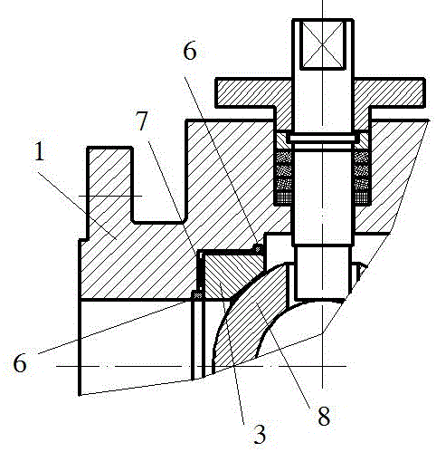
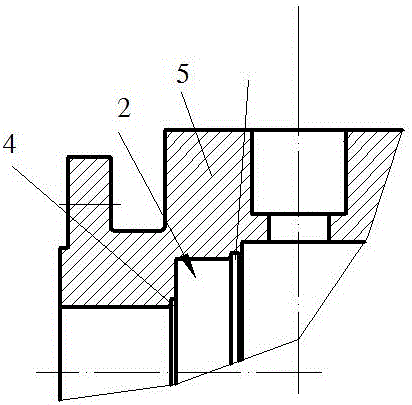
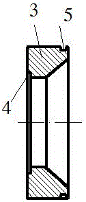
[0015] Embodiment 1: A metal valve seat installation structure of a ball valve with a protective structure, including a valve body 1, a metal valve seat hole 2 is opened in the center of the valve body 1, a metal valve seat 3 is installed in the metal valve seat hole 2, and a metal valve seat The first sealing groove 4 is provided on the horizontal connection end surface between the hole 2 and the metal valve seat 3, and the second sealing groove 5 is provided on the contact surface between the metal valve seat hole 2 and the side wall of the metal valve seat 3. A sealing ring 6 is arranged in the groove (4, 5), a wave spring 7 is arranged between the horizontal surface of the metal valve seat 3 and the horizontal end surface of the metal valve seat hole 2, and the spherical surface of the ball core 8 in the valve body 1 cooperates with the metal valve seat 3 for pre-tightening . The wave spring 7 is bent from stainless steel.

Embodiment 2

[0016] Embodiment 2: A metal valve seat installation structure of a ball valve with a protective structure, including a valve body 1, a metal valve seat hole 2 is opened in the center of the valve body 1, a metal valve seat 3 is installed in the metal valve seat hole 2, and the metal valve seat 3 There is a first sealing groove 4 on the horizontal end surface, a second sealing groove 5 is opened on the side wall of the metal valve seat 3, a sealing ring 6 is arranged in the first and second sealing grooves (4, 5), and the metal valve seat 3 A wave spring 7 is arranged between the horizontal surface and the horizontal end surface of the metal valve seat hole 2, and the spherical surface of the ball core 8 in the valve body 1 cooperates with the metal valve seat 3 for pre-tightening. The wave spring 7 is bent from stainless steel. The wave spring 7 is arranged in the gap between the first and second sealing grooves (4, 5).


PUM


Abstract

The invention discloses a ball valve metal valve seat mounting structure with a protective structure. The ball valve metal valve seat mounting structure comprises a valve body; a metal valve seat hole is formed in the center of the valve body; a metal valve seat is mounted in the metal valve seat hole; a first sealing groove is formed in a horizontal connecting end face of the metal valve seat hole and the metal valve seat; a second sealing groove is formed in a contact surface of the metal valve seat hole and the side wall of the metal valve seat; sealing rings are arranged in the first sealing groove and the second sealing groove; a wave spring is arranged between the horizontal plane of the metal valve seat and the horizontal end face of the metal valve seat hole; and a spherical surface of a ball core in the valve body is matched with the metal valve seat and pre-tightened. Pre-tightening force provided by the ball core is utilized for sealing, and a medium is prevented from entering a gap between the valve body and the metal valve seat, so that a protective effect is achieved.

Description

technical field [0001] The invention belongs to the technical field of general mechanical valves, in particular to a metal valve seat device with a protective structure for a ball valve. Background technique [0002] The Ball Valve is evolved from the Plug Valve. Its opening and closing part is a sphere, and the valve is opened and closed by rotating the sphere 90° around the axis of the valve stem. The ball valve not only has a simple structure and good sealing performance, but also has a small volume, light weight, less material consumption, small installation size, and the smallest flow resistance within a certain nominal diameter range. The ball valve also has a small driving torque and is easy to operate. It is easy to realize the advantages of fast opening and closing, and it is one of the fastest-growing valve varieties in the past ten years. There are two types of sealing methods for ball valves: soft seal and hard seal. Soft seal means that the valve seat is made o...

Claims


Application Information

Patent Timeline
Patent Type & Authority Applications(China)
IPC IPC(8): F16K5/06F16K5/08F16K5/20
CPCF16K5/06F16K5/08F16K5/20
Inventor 季林举王泽强
Owner ZHONGYI ENERGY SAVING & WEAR-RESISTANT TECH YIXING CO LTD
Why Eureka
Try Eureka