Supercharge Your Innovation With Domain-Expert AI Agents!

Main pipe of water separator

A water distributor and main pipe technology, applied in the direction of pipes, branch pipelines, pipes/pipe joints/pipe fittings, etc., can solve the problems of connection troubles and inaccessibility, and achieve the effect of easy positioning

Active Publication Date: 2016-11-09
ZHEJIANG DABLIN VALVE CO LTD
View PDF6 Cites 0 Cited by
  • Summary
  • Abstract
  • Description
  • Claims
  • Application Information

AI Technical Summary

Problems solved by technology

[0004] Although the above-mentioned combined water separator can make the centers of the water diversion holes on the outlet joints on the main body of each segment lie on the same straight line, the flanges with mounting holes are provided and the cooperation between the screw rod and the nut is used to adjust the distance between the segments. The positioning method of the main body formed by connecting the main body makes the connection more troublesome, and it is impossible to quickly position the centers of the water diversion holes on the same straight line on each segmented main body

Method used


Image

  • Main pipe of water separator
  • Main pipe of water separator
  • Main pipe of water separator

Examples


Embodiment 1

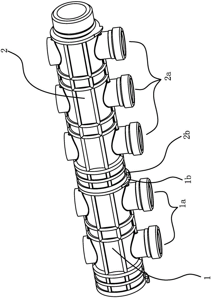
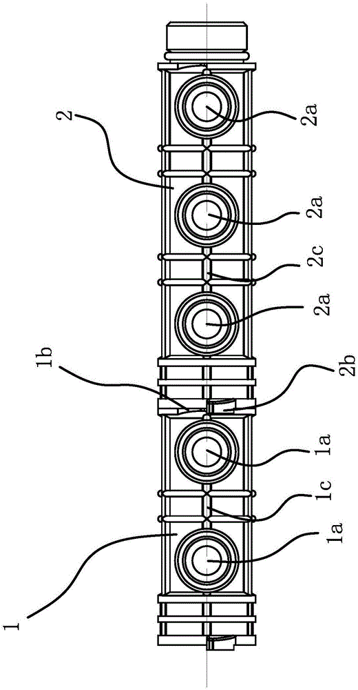
[0034] like figure 1 , figure 2 , Figure 5 , Image 6 and Figure 7 As shown, the main pipe of a water separator includes a first branch pipe 1 and a second branch pipe 2 arranged coaxially. The first branch pipe 1 is provided with a plurality of first water diversion holes 1a in the axial direction, and the second branch pipe 2 is arranged along the A number of second water diversion holes 2a are provided in the axial direction, and a protruding screw connection part 1d is provided at the center of one end of the first branch pipe 1. The screw connection part 1d is inserted into the corresponding end of the second branch pipe 2 and forms a screw connection , and a sealing ring 4 is provided outside the threaded portion 1d.

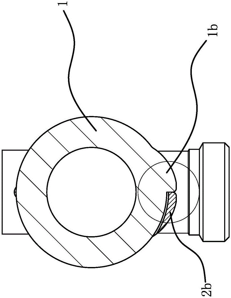
[0035] like figure 2 , image 3 , Figure 4 , Figure 5 and Image 6 As shown, there is a protruding abutting portion 1b on the outer side of one end where the first branch pipe 1 and the second branch pipe 2 are screwed together. Elongated, ...

Embodiment 2

[0042] The structure and principle of this embodiment are basically the same as that of Embodiment 1, the difference is that in this embodiment, the plane where the midline of the first rib 1c located outside the first branch pipe 1 is located is the same as the plane on the first branch pipe 1. The planes where the lines connecting the centers of the first water diversion holes 1a are perpendicular, the centerline of the first rib 1c and the abutment surface 1b1 on the abutment portion 1b are located on the same plane, so that the abutment surface 1b1 It is perpendicular to the plane where the line connecting the centers of the first water diversion holes 1a on the first branch pipe 1 is located; The plane where the connecting line between the centers of circles of the second water diversion holes 2a is perpendicular, the center line of the second convex rib 2c and the blocking surface 2b1 on the blocking portion 2b are located on the same plane, so that the blocking surface 2...


PUM


Abstract

The invention provides a main pipe of a water separator, belonging to the technical field of machinery. By adopting the main pipe of the water separator, the problem that the circular center of each water separation hole in the main pipe of a current combination-type water separator is difficult to position is solved. The main pipe comprises a first branch pipe and a second branch pipe which are coaxially arranged and are connected through threads; a plurality of first water separation holes are formed in the first branch pipe axially; a plurality of second water separation holes are formed in the second branch pipe axially; the outer side of the end, which is connected with the second branch pipe through threads, of the first branch pipe is provided with a convex relying part; the outer side of the end, which is connected with the first branch pipe through threads, of the second branch pipe is provided with a convex baffle part; and part of the baffle part extends out of the end surface, which is connected with the first branch pipe, of the second branch pipe along the axial direction of the second branch pipe; and when the relying part relies on the extending part of the baffle part on the second branch pipe, the circular centers of the first water separation holes in the first branch pipe and the circular centers of the second water separation holes in the second branch pipe are on the same straight line. The main pipe has the advantage that the circular centers of the water separation holes can be rapidly positioned on the same straight line.

Description

technical field [0001] The invention belongs to the technical field of machinery, and relates to a water distributor, in particular to a main pipe of the water distributor. Background technique [0002] The water separator is a water distribution and collection device for water supply and return in the water system. It is usually used in tap water supply systems, air-conditioning water systems, and floor heating systems. The water separator usually refers to the water supply direction, and it is called the water collector in the water return direction. At present, the main pipes of the water separators on the market are all one-piece structures made of copper. The main pipes of the water separators are provided with a number of water diversion holes along the axial direction. The number of water diversion holes determines the number of channels of the water separators. , it has been set at the factory, and the circuit cannot be quickly and flexibly assembled according to ac...

Claims


Application Information

Patent Timeline
IPC IPC(8): F16L41/03
CPCF16L41/03
Inventor 林海林李响林
Owner ZHEJIANG DABLIN VALVE CO LTD
Features
  • R&D
  • Intellectual Property
  • Life Sciences
  • Materials
  • Tech Scout
  • Unparalleled Data Quality
  • Higher Quality Content
  • 60% Fewer Hallucinations
Learn More