Integral combined type dehumidification constant-temperature heat pump device for swimming pool

A swimming pool and combined technology, which is applied in the field of integrated dehumidification and constant temperature heat pump devices for swimming pools, can solve the problems of complicated installation, repeated debugging, and high installation costs, and achieve the effects of stable host operation, simple system installation, and saving installation space

Active Publication Date: 2016-11-09
广东威浪仕水环境设备有限公司
View PDF8 Cites 7 Cited by
  • Summary
  • Abstract
  • Description
  • Claims
  • Application Information

AI Technical Summary

Problems solved by technology

[0003] However, there are deficiencies in the actual installation process. The existing dehumidification heat pumps for swimming pools must be equipped with an outdoor cooling condenser to form a complete system for processing, and the heat generated during cooling and dehumidification is discharged to the outside to ensure dehumidification. Indoor air temperature does not rise during the process
The installation of outdoor heat dissipation condenser is complicated and complicated. Generally, non-professionals cannot install it, and an outdoor location suitable for installation must be arranged. If the place used does not have the install

Method used


Image

  • Integral combined type dehumidification constant-temperature heat pump device for swimming pool
  • Integral combined type dehumidification constant-temperature heat pump device for swimming pool

Examples


Embodiment Construction

[0029] Embodiments of the present invention are described in detail below, examples of which are shown in the drawings, wherein the same or similar reference numerals designate the same or similar elements or elements having the same or similar functions throughout. The embodiments described below by referring to the figures are exemplary only for explaining the present invention and should not be construed as limiting the present invention.

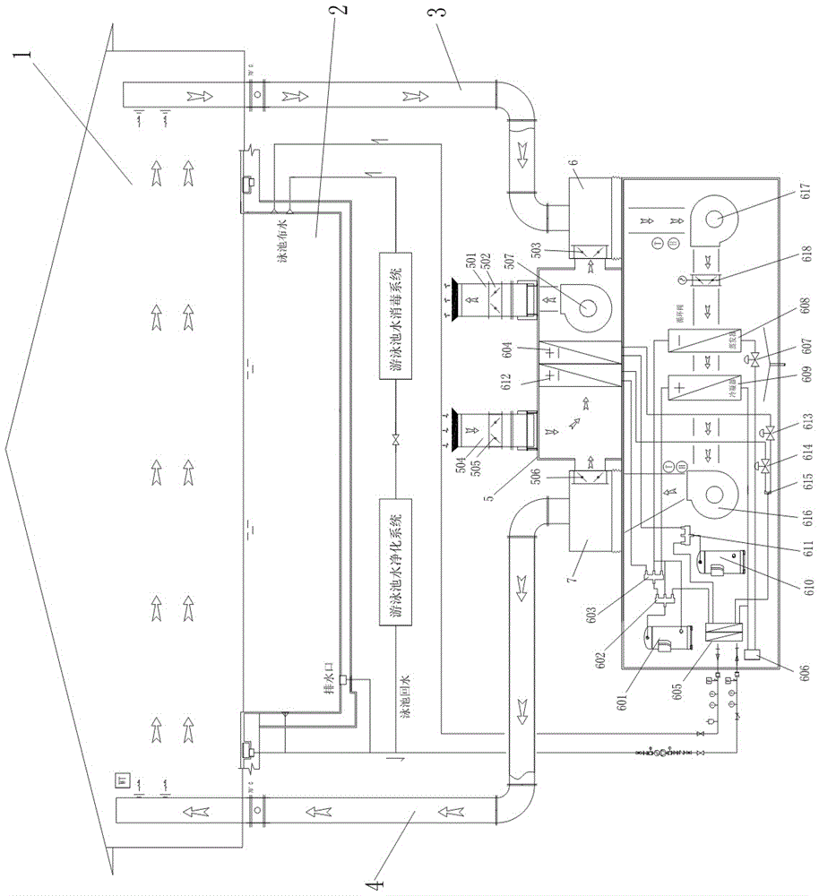
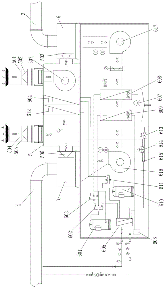
[0030] Such as figure 1 As shown, the swimming pool 2 is provided with a water outlet and a water inlet respectively, and a purification system and a disinfection system are arranged between the water outlet and the water inlet. The filtration of the purification system makes the pool water purified, and the disinfection system disinfects it by adding chemicals , flocculation, algae removal and other treatments, and then make the pool water clean and hygienic through the action of physical processes. A water circulation pipeline is also...


PUM


Abstract

The invention particularly relates to an integral combined type dehumidification constant-temperature heat pump device for a swimming pool. The integral combined type dehumidification constant-temperature heat pump device for the swimming pool comprises a swimming hall, the swimming pool and a dehumidification heat pump unit. The swimming pool is located in the swimming hall. The dehumidification heat pump unit is located in a machine room of the swimming hall. An air circulation pipeline in the swimming hall is connected with the dehumidification heat pump unit. A water circulation pipeline in the swimming pool is connected with the dehumidification heat pump unit. A built-in installation room used for supplementing fresh air into the swimming hall is arranged on the dehumidification heat pump unit. An air inlet and an air outlet of the built-in installation room communicate with air outside the swimming hall. The built-in installation room is provided with a first-stage built-in heat exchanger and a second-stage built-in heat exchanger, and the first-stage built-in heat exchanger and the second-stage built-in heat exchanger are used for cooling or heating air flowing through the first-stage built-in heat exchanger and the second-stage built-in heat exchanger. The first-stage built-in heat exchanger and the second-stage built-in heat exchanger are connected with the dehumidification constant-temperature heat pump unit. The integral combined type dehumidification constant-temperature heat pump device for the swimming pool has the beneficial effects that through the built-in installation room arranged on the dehumidification heat pump unit, re-debugging is not needed when the whole device is installed, installation is convenient, and installation space is saved.

Description

technical field [0001] The invention specifically relates to an integral combined dehumidification constant temperature heat pump device for a swimming pool. Background technique [0002] There is hot and humid air in the swimming pool or hot spring area during use. Generally, the heat pump unit is used for dehumidification. More specifically, the hot and humid air on the surface of the swimming pool is extracted by the return fan, and then enters the dehumidification heat pump unit through the return air line for dehumidification. Among them, in order to meet the human body's demand for oxygen, we will discharge part of the old indoor air and replace it with some fresh air to ensure that there will be no possibility of excessive carbon dioxide in the swimming pool or hot spring area. The proportion is generally around 10%-20%; After the humid hot air has passed through the filter in the dehumidification heat pump unit, the dust and particles in the air are filtered out an...

Claims


Application Information

Patent Timeline
IPC IPC(8): F24F3/052F24F3/14F24F13/28
CPCF24F3/052F24F3/14F24F13/28F24F2203/12
Inventor 吕伯基陈锦标
Owner 广东威浪仕水环境设备有限公司
Why Eureka
Try Eureka