Parallel arrangement connection portion and end cover sealing structure for loop type heat pipe

A closed structure and group connection technology, which is applied in indirect heat exchangers, lighting and heating equipment, etc., can solve the problems of reduced heat dissipation efficiency, complex structure composition, mutual obstruction of flow directions, etc.

Inactive Publication Date: 2016-11-09
SUZHOU FORCECON ELECTRIC
View PDF7 Cites 2 Cited by
  • Summary
  • Abstract
  • Description
  • Claims
  • Application Information

AI Technical Summary

Problems solved by technology

[0002] In view of the internal structure design of the early heat pipe, the steam flow path and the condensate flow path were arranged in the same pipe section space and were arranged in an overlapping state, so that the flow directions conflicted with each other and hindered each other, resulting in reduced heat dissipation efficiency and other problems. The industry has developed a loop-type heat pipe structure. In this heat pipe structure, the steam flow path and the condensate flow path are set in different sections in the heat pipe space, and the overall form of a loop form can solve the aforementioned problems.
[0003] However, the existing loop-type heat pipe structure that can be seen at present still has its shortcomings. The two ends are spaced apart from each other, and a base is set between the two ends. The base is provided with a connecting channel, and the two ends of th

Method used


Image

  • Parallel arrangement connection portion and end cover sealing structure for loop type heat pipe
  • Parallel arrangement connection portion and end cover sealing structure for loop type heat pipe
  • Parallel arrangement connection portion and end cover sealing structure for loop type heat pipe

Examples


Embodiment

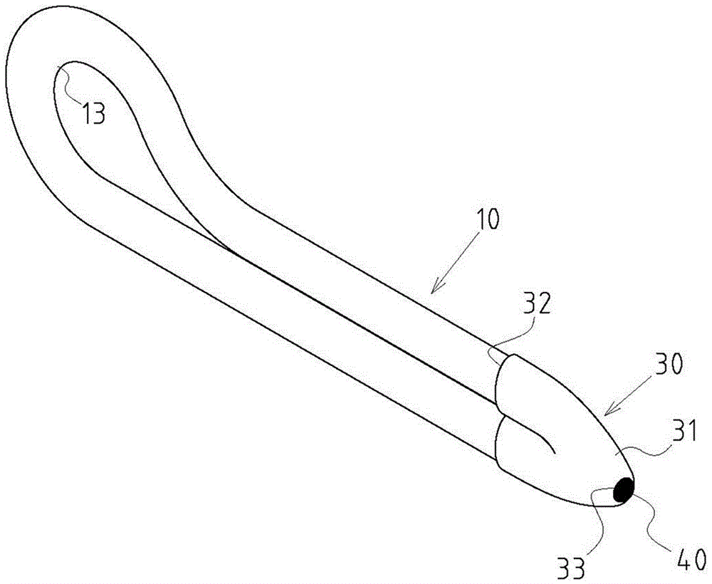
[0027] Example: see Figure 1~5 Shown is a preferred embodiment of the end cap closure structure of the parallel connection part of the loop heat pipe of the present invention, but these embodiments are for illustration purposes only, and are not limited by this structure in the patent application.

[0028] The closure structure of the end cover of the parallel connection part of the loop type heat pipe includes the following components:

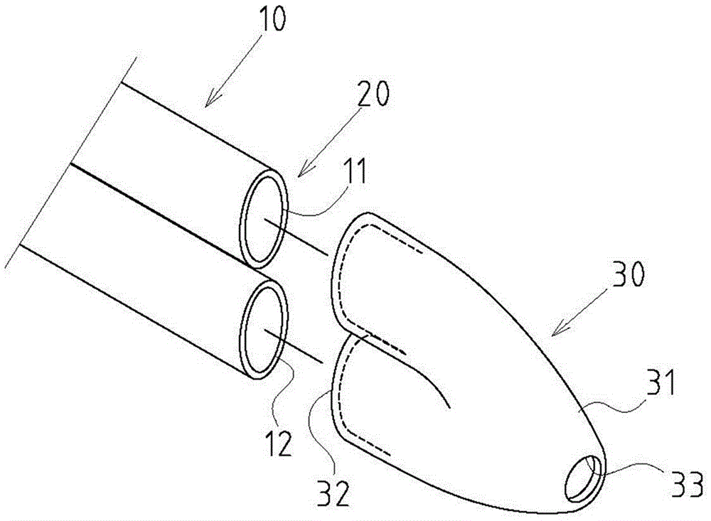
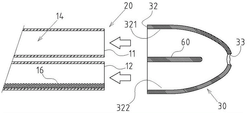
[0029] A hollow tube body 10 is bent into a folded shape and includes two tube ports 11, 12 and a loop-type section 13 between the two tube ports 11, 12, and the hollow tube body 10 has a flow channel inside Space 14, the channel space 14 includes an evaporation section 141 and a condensation section 142 (only marked in Figure 5 ) and accommodate a working fluid 15; and at least the evaporating section 141 is provided with a capillary 16; a group of connecting parts 20, the two tube ports 11, 12 passing through the hollow tube body 10 are ...


PUM


Abstract

A parallel arrangement connection portion and end cover sealing structure for a loop type heat pipe is characterized by mainly comprising a hollow pipe body, a parallel arrangement connection portion and a sealing end cover, wherein the hollow pipe body is bent into the inflection form and comprises two pipe end openings and a loop type section, a runner space in the hollow pipe body comprises an evaporation section and a condensation section and contains working fluid, and a capillary structure is at least arranged at the evaporation section; the parallel arrangement connection portion is formed in the form that the two pipe end openings passing the hollow pipe body are the same in orientation, and pipe bodies are arranged in parallel; the sealing end cover is in the form of a cap cover and comprises a sealing end and a nesting arrangement end, the nesting arrangement end comprises at least one nesting opening and the two pipe end openings which are arranged on the parallel arrangement connection portion in a nesting arrangement manner and are in an airtight state, the sealing end is provided with an air removal hole, and the air removal hole is sealed to be in the airtight form after completing the vacuumizing air removal state in the runner space in the hollow pipe body. The parallel arrangement connection portion and end cover sealing structure has the practical progressiveness that manufacturing, machining and forming are easier, manufacturing cost is lowered, and the airtightness effect is good and the good industrial economic benefits.

Description

technical field [0001] The invention relates to a loop-type heat pipe, in particular to an innovative end-cap-type closed structure of the parallel connection part of the loop-type heat pipe. Background technique [0002] In view of the internal structure design of the early heat pipe, the steam flow path and the condensate flow path were arranged in the same pipe section space and were arranged in an overlapping state, so that the flow directions conflicted with each other and hindered each other, resulting in reduced heat dissipation efficiency and other problems. The industry has developed a loop-type heat pipe structure. In this heat pipe structure, the steam flow path and the condensate flow path are set in different sections in the heat pipe space, and form a loop form as a whole, so as to solve the aforementioned problems. [0003] However, the existing loop-type heat pipe structure that can be seen at present still has its shortcomings. The two ends are spaced apart...

Claims


Application Information

Patent Timeline
IPC IPC(8): F28D15/02F28D15/04
CPCF28D15/0266F28D15/04
Inventor 何信威黄志仁叶肇浩
Owner SUZHOU FORCECON ELECTRIC
Why Eureka
Try Eureka