Shield tunnel segment joint fixed point sensing optical cable two-dimensional deformation monitoring method

A technology for shield tunneling and deformation monitoring, applied in the fields of tunnel engineering, geotechnical engineering, and surveying engineering, to achieve unattended automatic monitoring data collection, remote control monitoring data collection and transmission, and slow deformation development

Inactive Publication Date: 2016-11-09
NANJING UNIV +2
View PDF6 Cites 21 Cited by
  • Summary
  • Abstract
  • Description
  • Claims
  • Application Information

AI Technical Summary

Problems solved by technology

Especially the two-dimensional deformation monitoring method and system of shield tunnel segment joints with fixed-point sensing optical cable

Method used


Image

  • Shield tunnel segment joint fixed point sensing optical cable two-dimensional deformation monitoring method
  • Shield tunnel segment joint fixed point sensing optical cable two-dimensional deformation monitoring method
  • Shield tunnel segment joint fixed point sensing optical cable two-dimensional deformation monitoring method

Examples


Embodiment Construction

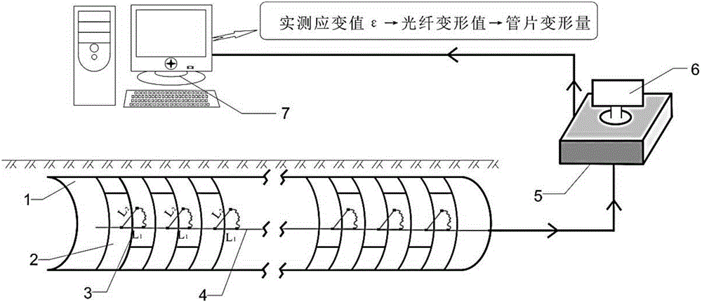
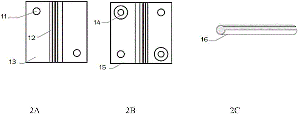
[0038] figure 1 , 2 Middle, 1-shield tunnel; 2-shield tunnel segment; 3-segment joint; 4-test optical cable; 5-distributed demodulator; 6-monitor; 7-data processing system; L 1 Open and close test sections for segment seams; L 1 It is the test section for segment seam staggering, L 2 It is the test section for segment seam staggering. . 11-threaded hole; 12-cable fixing slot; 13-clamp male piece; 14-riveting hole; 15-clamp female piece; 16-protective sleeve. The overall schematic diagram of the two-dimensional deformation monitoring system of shield segment joints based on optical fiber fixed-point monitoring technology.

[0039] Brief description of the monitoring system: The monitoring device involved in the monitoring system is composed of sensing optical cable, fixing fixture, protective sleeve, signal transmission optical cable, optical fiber demodulator and data processing software. The fixing fixtures are arranged on the joints of the segments to be monitored acco...


PUM


Abstract

The invention discloses a shield tunnel joint fixed point two-dimensional deformation monitoring method based on a distributed fixed point sensing technology. Distributed optical fibers are utilized to collect deformation (strain) information; customized sensing optical cables which are installed on adjacent segments in an orthogonal or oblique crossing mode are utilized to measure the two-dimensional deformation condition of the joint between the two adjacent segments, and the integral deformation condition and local segment deformation conditions of a tunnel are obtained; and the sensing optical cables are used as sensors, the sensing optical cables are used to sense the distance between adjacent fixed clamps and the deformation change so as to realize the two-dimensional deformation monitoring of the shield tunnel, and different sensing optical cables are selected according to the demodulation technology and different monitoring construction environments. The system comprises the sensing optical cables, the fixed clamps, protection sleeves, a signal transmission optical cable and an optical signal demodulator. According to the invention, distributed measurement on the deformation of the shield tunnel segment joint is carried out in real time, and the method has the advantages that distributed monitoring is realized, the monitoring range is large, the sensing device is simple, the installation is convenient, and automatic monitoring is realized.

Description

technical field [0001] The invention belongs to the fields of tunnel engineering, geotechnical engineering and surveying engineering, and in particular relates to a distributed monitoring method capable of testing the tension and shrinkage deformation of shield segment joints in real time. Background technique [0002] Shield method construction has become a common construction method for urban subway construction due to its advantages of high degree of automation, fast construction speed, no influence of climate, and little impact on ground buildings and ground traffic. The health monitoring of shield tunnel is an essential work related to the safety of train operation and the safety of people's life and property. [0003] The structural stiffness of the shield tunnel spliced ​​by prefabricated segments is significantly lower than that of the segments, so the overall deformation of the tunnel is often concentrated on the opening, closing or dislocation of the segment joints...

Claims


Application Information

Patent Timeline
Patent Type & Authority Applications(China)
IPC IPC(8): G01B11/16E21F17/18
CPCG01B11/16E21F17/18G01B11/18
Inventor 施斌王兴王占生魏广庆李文峰刘建国孟志浩张振
Owner NANJING UNIV
Why Eureka
Try Eureka