Structure deformation device based on fiber sensing and detection method thereof

A technology of structural deformation and optical fiber sensing, which is applied in the direction of using optical devices to transmit sensing components, mechanical solid deformation measurement, etc., can solve problems such as low measurement accuracy, and achieve the effect of improving accuracy

Pending Publication Date: 2019-06-21
南京智慧基础设施技术研究院有限公司 +1
View PDF1 Cites 2 Cited by
  • Summary
  • Abstract
  • Description
  • Claims
  • Application Information

AI Technical Summary

Problems solved by technology

[0007] The purpose of the present invention is to overcome the deficiencies of the above-mentioned traditional technologies, aiming at the defect of low measurement accuracy caused by the deformation of the existing optical fiber gas sensor or optical fiber liquid sensor, to design a device that can detect the deformation of the optical fiber sensor

Method used


Image

  • Structure deformation device based on fiber sensing and detection method thereof
  • Structure deformation device based on fiber sensing and detection method thereof
  • Structure deformation device based on fiber sensing and detection method thereof

Examples


Embodiment 1

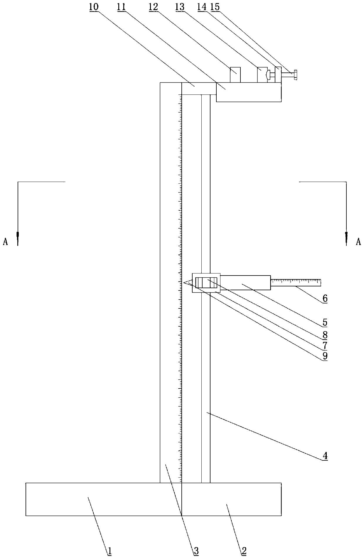
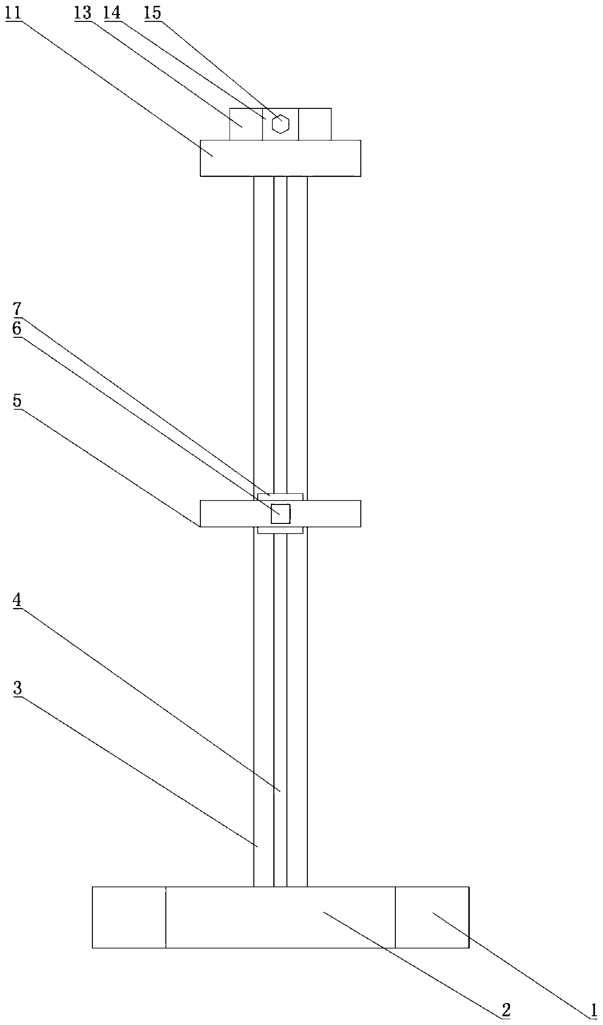
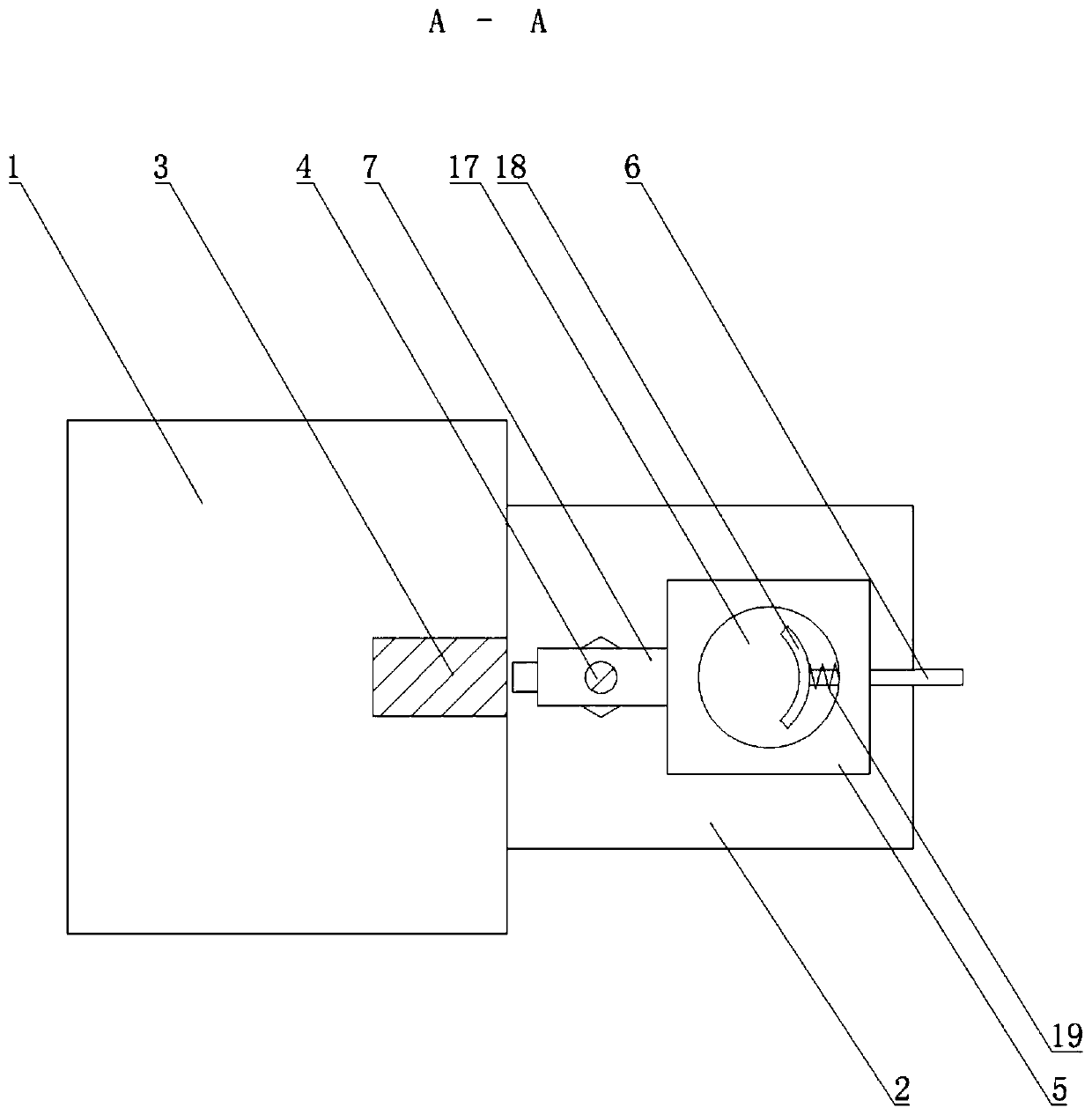
[0023] Example 1: as attached Figure 1-4 As shown in the figure, a structure deformation device based on optical fiber sensing includes a frame on which a main support rod is fixed in the vertical direction, and an optical fiber locking rod is fixed at one end of the main support rod away from the frame. An optical fiber peripheral dimension measuring device with adjustable position is arranged between the optical fiber locking device and the frame.

[0024] The optical fiber locking device includes an optical fiber grooming frame 11 . The optical fiber grooming frame 11 is provided with an optical fiber passing hole 16 , and the optical fiber passing hole 16 passes through the optical fiber grooming frame 11 .

[0025] The side of the optical fiber passing hole 16 away from the frame is provided with a clamping clamp mechanism, and the clamping clamp mechanism includes a first arc-shaped plate 12 that is fixedly arranged on the optical fiber guide frame 11 and cooperates wit...

Embodiment 2

[0029] Example 2: as attached Figure 1-4 As shown in the figure, a structure deformation device based on optical fiber sensing includes a frame on which a main support rod is fixed in the vertical direction, and an optical fiber locking rod is fixed at one end of the main support rod away from the frame. An optical fiber peripheral dimension measuring device with adjustable position is arranged between the optical fiber locking device and the frame.

[0030] The optical fiber locking device includes an optical fiber grooming frame 11 . The optical fiber grooming frame 11 is provided with an optical fiber passing hole 16 , and the optical fiber passing hole 16 passes through the optical fiber grooming frame 11 .

[0031] The side of the optical fiber passing hole 16 away from the frame is provided with a clamping clamp mechanism, and the clamping clamp mechanism includes a first arc-shaped plate 12 that is fixedly arranged on the optical fiber guide frame 11 and cooperates wit...


PUM


Abstract

The invention provides a structure deformation device based on fiber sensing. The device includes a frame and is characterized in that the frame is fixedly provided with a main supporting rod in the vertical direction, one end of the main supporting rod away from the frame is fixedly provided with a fiber locking device, and a position-adjustable fiber peripheral dimension measurement device is arranged between the fiber locking device and the frame. The device is advantaged in that deformation of the fiber sensor structure can be monitored, reliability of the fiber sensor can be determined according to the deformation dimension, and measurement accuracy of a fiber sensor is improved.

Description

technical field [0001] The present invention relates to the technical field of optical fiber sensors. [0002] Specifically, it relates to a detection method of a structure deformation device based on optical fiber sensing. Background technique [0003] Optical fiber gas sensors or optical fiber liquid sensors have been widely used due to their advantages of good electrical insulation, strong anti-electromagnetic interference, explosion-proof, long-distance long-term online measurement, simple structure of the sensing unit, stability and reliability, and easy formation of optical fiber sensing networks. It is used for the detection of various toxic and harmful gases or liquid substances, air pollution and industrial waste gas, industrial wastewater monitoring, and the detection of food and living environment quality. Optical fiber gas sensors or optical fiber liquid sensors include spectral absorption type, fluorescence type, dye indicator type, refractive index change type...

Claims


Application Information

Patent Timeline
Patent Type & Authority Applications(China)
IPC IPC(8): G01B5/30G01D5/353
Inventor 吴智深黄璜唐永圣方达
Owner 南京智慧基础设施技术研究院有限公司
Why Eureka
Try Eureka