
Downhole Oil-Water Interface Detector

An oil-water interface and detector technology, which is applied to the liquid level indicator for physical variable measurement and other directions, can solve the problems of poor detection effect of downhole detection sensors, and achieve the effect of high measurement accuracy.

Active Publication Date: 2020-03-10
BC P INC CHINA NAT PETROLEUM CORP +1
View PDF6 Cites 0 Cited by
  • Summary
  • Abstract
  • Description
  • Claims
  • Application Information

AI Technical Summary

Problems solved by technology

[0006] The main purpose of the present invention is to provide a downhole oil-water interface detector to solve the problem of poor detection effect of downhole detection sensors in the prior art

Method used


Image

  • Downhole Oil-Water Interface Detector
  • Downhole Oil-Water Interface Detector
  • Downhole Oil-Water Interface Detector

Examples


Embodiment Construction

[0033] It should be noted that, in the case of no conflict, the embodiments in the present application and the features in the embodiments can be combined with each other. The present invention will be described in detail below with reference to the accompanying drawings and examples.

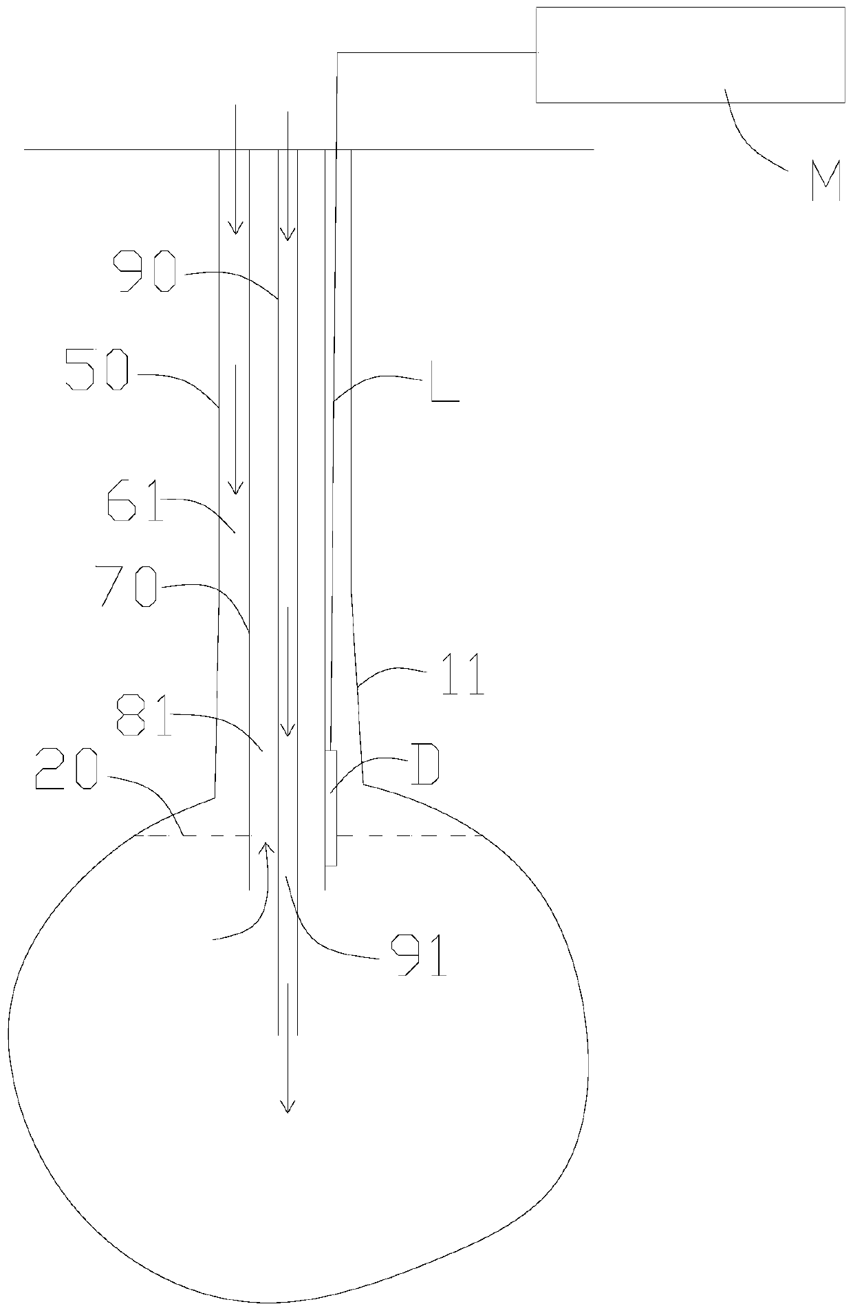
[0034] Such as Figures 1 to 5 As shown, in the process of cavitation, water is injected through the cavitation inner tube 90 , the cavitation inner tube 90 is covered with the cavitation outer tube 70 , and the cavitation outer tube 70 is covered with the casing 50 . The inner cavity 91 of the cavity-making inner tube 90 is a water injection channel, the inner annular channel 81 between the cavity-making outer tube 70 and the cavity-making inner tube 90 is a channel for discharging brine, and the outer tube between the casing 50 and the cavity-making outer tube 70 The annular passage 61 is a passage for injecting diesel oil. Below the casing 50 is the open hole section 11 .

[0035] During ...


PUM


Abstract

The invention provides a downhole oil-water interface detector which comprises a detection sensor D and a ground detector M. A plurality of detection structures are arranged on the detection sensor D, first ends of the multiple detection structures are electrically connected with one another, second ends of the multiple detection structures are connection contact points which are sequentially arranged along the height directions of the detection structures at intervals, and each detection structure comprises a detection resistor R; the ground detector M is connected with the detection sensor D, measurement voltages Vc can be outputted to the detection sensor D by the ground detector M, and measurement currents Ic which flow through the detection sensor D can be detected by the ground detector M, so that the heights of oil-water interfaces can be judged according to the measurement currents Ic. The downhole oil-water interface detector has the advantage that detection effects can be improved by the downhole oil-water interface detector.

Description

technical field [0001] The invention relates to the technical field of underground salt cavern gas storage cavity construction engineering, in particular to an underground oil-water interface detector. Background technique [0002] Cavity construction of salt cavern gas storage refers to the injection of fresh water or unsaturated brine into the underground salt layer under certain control conditions, through the dissolution of salt rock and discharge of brine, thereby forming a storage space of a specific shape underground. In order to ensure the implementation of the project, it is necessary to inject fresh water into the underground salt layer from the cavity-building inner pipe in the wellbore. The annulus is continuously drained to the surface, thereby creating a volumetric space in the subsurface salt formation. In order to ensure that the space has a stable shape, it is necessary to inject diesel oil as a protective layer material into the annulus between the outer p...

Claims


Application Information

Patent Timeline
Patent Type & Authority Patents(China)
IPC IPC(8): G01F23/22
Inventor 吴国明申瑞臣袁光杰田中兰杨海军屈丹安路立君杨松李萍徐宝财李建君巴金红
Owner BC P INC CHINA NAT PETROLEUM CORP
Learn More