

Evaluation testing method for damage of drilling fluid to compact gas reservoir
An experimental method and drilling fluid technology, applied in the direction of material inspection, suspension and porous material analysis, analysis by nuclear magnetic resonance, etc., can solve the problem of strong heterogeneity of core, loss of core thickness, poor repeatability and reproducibility of experiments, etc. question
Inactive Publication Date: 2016-11-09
SOUTHWEST PETROLEUM UNIV
View PDF3 Cites 44 Cited by
- Summary
- Abstract
- Description
- Claims
- Application Information
AI Technical Summary
Problems solved by technology
[0015] Using the core damage rate (DR) as the damage index method, the experiment uses the ratio of the permeability of the whole core before and after contamination to reflect the degree of damage to the reservoir by the drilling fluid, and there is no uniform standard for the length of the core
This method considers that the entire core has been damaged, so the evaluation cannot truly reflect the damage degree of the reservoir. In addition, the difference in the length of the core will have a great impact on the evaluation results; Thickness loss and damage, poor repeatability and reproducibility of the experiment, and strong heterogeneity of the core, it is difficult to control the process of measuring the permeability of the remaining rock samples to be constant; the resistivity method determines the invasion depth, and the measured resistivity and permeability The rate is the average value of the core section between the two measuring points. For the core with non-uniform intrusion, the value on the section is generally not equal to the measured average value.
The penetration depth and damage pollution degree obtained by the experiment are difficult to reflect the objective facts
[0016] In the method of determining the damage depth by using the core damage rate (SDR) of each section, the slice method needs to destroy the core, and the permeability of each section of the core before pollution can only be regarded as uniform, and the evaluation of the damage degree of each section is not true; although the gradient method does not need Destroying the core can also monitor the pollution process in real time, but the experiment requires high pressure measurement accuracy
[0017] In addition, there are some common problems in the above experiments: the initial value of the drilling fluid damage permeability change is the dry core or the permeability when the core is saturated with irreducible water, rather than the original water saturation S of the formation. wi state permeability, the evaluation results cannot reflect the degree of damage under formation conditions; the low-pressure core saturated formation water used in most experiments is not suitable for tight sandstone; the air-drying, drying, and gas-flooding methods to establish core water saturation are difficult to ensure water in the The uniform distribution in the core has an impact on the evaluation of drilling fluid invasion damage results; for the evaluation of tight and ultra-tight sandstone drilling fluid invasion damage, it is often difficult to test the permeability due to the large decrease in local permeability after damage, resulting in the overall damage degree of the core Strong artifacts, and the test time is too long, the water saturation of the core sample will change greatly, which will affect the test results; the experimental evaluation index is mainly the permeability change rate, and the invasion depth of the liquid and solid phases of the drilling fluid cannot be determined
Method used
View moreImage
Smart ImageViewing Examples

Examples
Embodiment
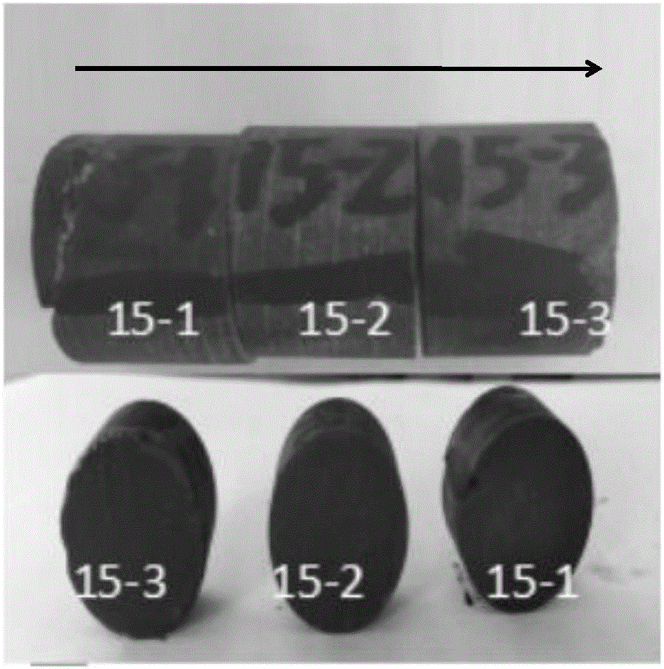
[0074] Taking the tight sandstone core of the Kelasu gas field as an example, according to the well test data, the original water saturation of the reservoir S wi 25-35%. Select 6 tight sandstone cores and use the method of the invention to evaluate the damage degree of drilling fluid invasion. Here, No. 15 core sample is adopted as the experimental object, and the experimental method for evaluating the damage of drilling fluid in tight gas reservoirs provided by the present invention comprises the following steps:
Login to View More PUM
 Abstract
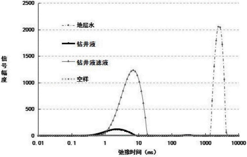
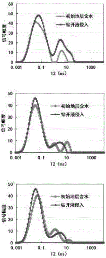
A disclosed evaluation testing method for damage of a drilling fluid to a compact gas reservoir comprises the following steps: drying a core sample, marking, performing uniform segmenting and slicing, and measuring the weight and other parameters of the dry core sample; putting the core segments into a fluid for infiltration and saturation; performing reverse centrifugation operation on the core segments, and acquiring the original water saturation Swi of the small core segment samples; measuring the nuclear magnetic resonance T2 spectrums of simulated stratum water and a filtrate of the drilling fluid and determining the difference; performing NMR imaging measurement on the fluid distribution state in the core; and putting the core segments into a core clamper of a drilling-fluid circulating instrument for measurement after the drilling fluid is circulated and calculating the water saturation Swi and the gas permeability K2 of the core segments, calculating the permeability damaging rate after infiltration of the drilling fluid by using the measurement results through comparison, so as to evaluate the damage degree caused by infiltration of the drilling fluid at different depths. The novel evaluation testing method for damage of a drilling fluid to compact and super compact gas reservoirs is established by improving an original slice method.
Description
technical field [0001] The invention relates to the field of oil and gas field development, in particular to an experimental method for evaluating drilling fluid damage during the drilling process of tight sandstone gas reservoirs. Background technique [0002] During positive differential pressure drilling, solid particles and liquid phases in the drilling fluid will inevitably invade the reservoir under the action of differential pressure, changing the original state of reservoir fluid distribution near the wellbore and possibly causing reservoir damage. Potential damage mainly includes four types: 1) Filtrate damage to the reservoir: under the action of the difference between the fluid column pressure in the well and the reservoir pressure, the filtrate enters the reservoir. The filtrate can cause the clay in the reservoir to hydrate and expand, or cause particles such as clay minerals in the reservoir to disperse and migrate to block the pores of the reservoir and cause ...
Claims
Login to View More Application Information
Patent Timeline
 IPC IPC(8): G01N33/00G01N33/24G01N15/08G01N24/08
CPCG01N15/08G01N24/081G01N33/00G01N33/24G01N2015/0813
Inventor唐洪明王猛屈海洲张烈辉李玲赵峰王俊杰王翼君
OwnerSOUTHWEST PETROLEUM UNIV