A double-terminal fault location method for double-circuit DC transmission lines on the same tower with wave velocity correction
A DC transmission line, double-circuit technology on the same tower, applied in the direction of fault location, fault detection according to conductor type, etc., can solve problems such as line length deviation, affecting distance measurement accuracy, etc.
- Summary
- Abstract
- Description
- Claims
- Application Information
AI Technical Summary
Problems solved by technology
Method used
Image
Examples
Embodiment 1
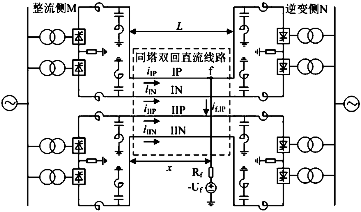
[0070] Example 1: Establish as attached figure 1 As shown, the Xiluodu-Guangdong ±500kV double-circuit DC transmission system on the same tower is used as the simulation model. Each pole of the system consists of two 12-pulse converters connected in series, and the total length of the DC transmission line is 1286km. 0.3H smoothing reactors are installed on both sides of the line. Assume now that a ground fault occurs 400km away from the rectifier side M terminal of the secondary negative line IIN, and the transition resistance is 0Ω.
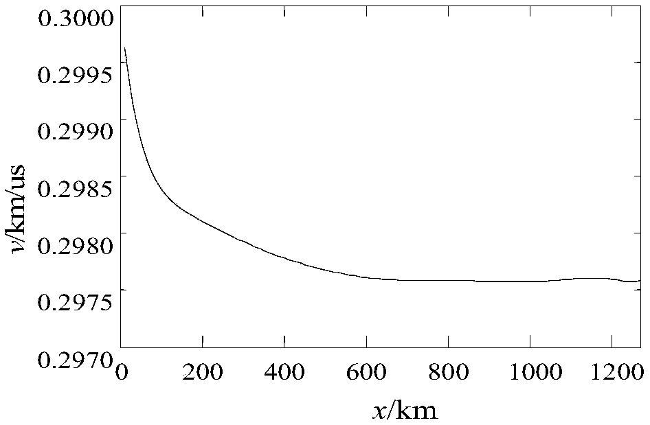
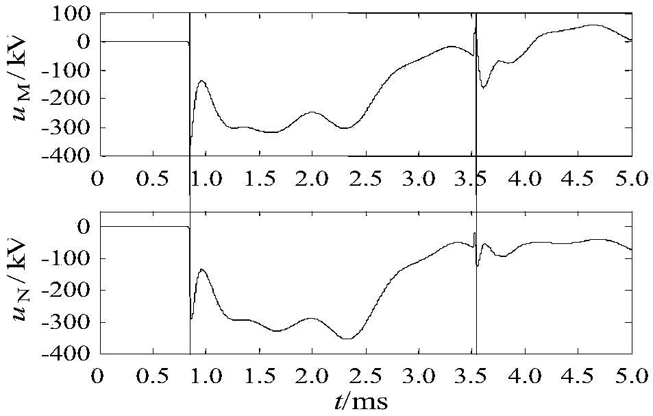
[0071] According to the first step, the arrival time of the line-mode fault component voltage on the rectifier side and the inverter side is obtained: the phase-mode transformation matrix is used to decouple the fault component voltage on the rectifier side and the inverter side after a single-pole ground fault occurs on the transmission line, and the line-mode fault component voltage is obtained. Fault component voltage traveling wave u M...
Embodiment 2
[0072] Example 2: Establish as attached figure 1 As shown, the Xiluodu-Guangdong ±500kV double-circuit DC transmission system on the same tower is used as the simulation model. Each pole of the system consists of two 12-pulse converters connected in series, and the total length of the DC transmission line is 1286km. 0.3H smoothing reactors are installed on both sides of the line. Assume now that a ground fault occurs 860km away from the rectifier side M terminal on the positive line IP, and the transition resistance is 200Ω.
[0073] According to the first step, the arrival time of the line-mode fault component voltage on the rectifier side and the inverter side is obtained: use the decoupling transformation matrix to decouple the fault component voltage on the rectifier side and the inverter side after a unipolar ground fault occurs on the transmission line, and obtain the line-mode fault component voltage Mode fault component voltage traveling wave u M,mode with u N,mode ...
PUM
 Abstract
Description
Claims
Application Information
 - R&D
- Intellectual Property
- Life Sciences
- Materials
- Tech Scout
- Unparalleled Data Quality
- Higher Quality Content
- 60% Fewer Hallucinations
Browse by: Latest US Patents, China's latest patents, Technical Efficacy Thesaurus, Application Domain, Technology Topic, Popular Technical Reports.
© 2025 PatSnap. All rights reserved.Legal|Privacy policy|Modern Slavery Act Transparency Statement|Sitemap|About US| Contact US: help@patsnap.com


