Eureka AIR delivers breakthrough ideas for toughest innovation challenges, trusted by R&D personnel around the world.

A Calculation Method of Main and Minor Lobe Ground-sea Clutter Main Distribution under Radar Downsight and Tail Detection

A technology of distributed computing and sea clutter, applied to radio wave measurement systems, instruments, etc., can solve problems that affect the performance of radar detection and tracking targets, and achieve the effect of strong real-time computing

Active Publication Date: 2019-01-08
SHANGHAI RADIO EQUIP RES INST
View PDF2 Cites 0 Cited by
  • Summary
  • Abstract
  • Description
  • Claims
  • Application Information

AI Technical Summary

Problems solved by technology

[0003] The purpose of the present invention is to provide a method for calculating the main distribution of the main and minor lobes of the ground-sea clutter under the radar down-sight rear detection, which can obtain the accurate position of the main distribution of the ground-sea clutter in the range-Doppler domain through online calculation, and solve the problem of Strong sidelobe clutter seriously affects the performance of radar down-look and tail detection and tracking targets, so that the target echo signal avoids strong side-lobe clutter and falls into strong side-lobe clutter when the radar looks behind the tail and detects targets The area provides the necessary reference conditions to effectively improve the detection power and tracking performance of the radar under the radar

Method used


Image

  • A Calculation Method of Main and Minor Lobe Ground-sea Clutter Main Distribution under Radar Downsight and Tail Detection
  • A Calculation Method of Main and Minor Lobe Ground-sea Clutter Main Distribution under Radar Downsight and Tail Detection
  • A Calculation Method of Main and Minor Lobe Ground-sea Clutter Main Distribution under Radar Downsight and Tail Detection

Examples


Embodiment Construction

[0042] The present invention will be further elaborated below by describing a preferred specific embodiment in detail in conjunction with the accompanying drawings.

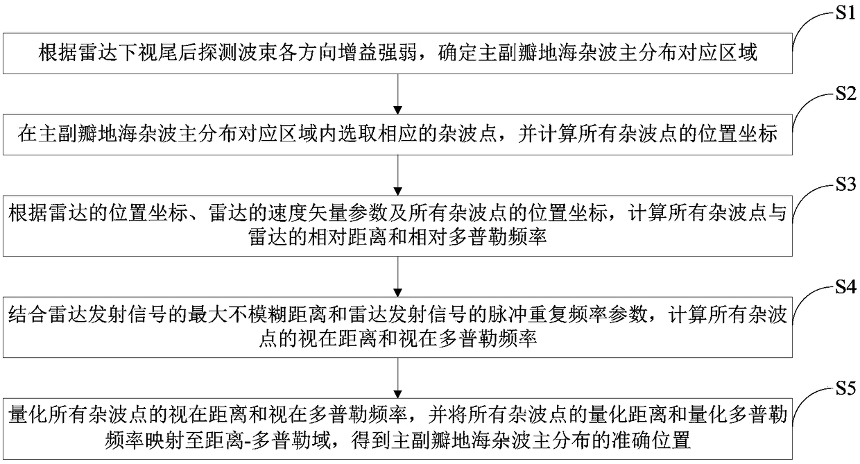
[0043] like figure 1 As shown, a method for calculating the main distribution of the main and side lobes ground-sea clutter under radar down-sight tail detection, including the following steps:

[0044] S1. According to the strength of the gain in each direction of the radar downsight and rear detection beam, determine the corresponding area of ​​the main distribution of the main and secondary lobes and sea clutter.

[0045] Step S1 specifically includes:

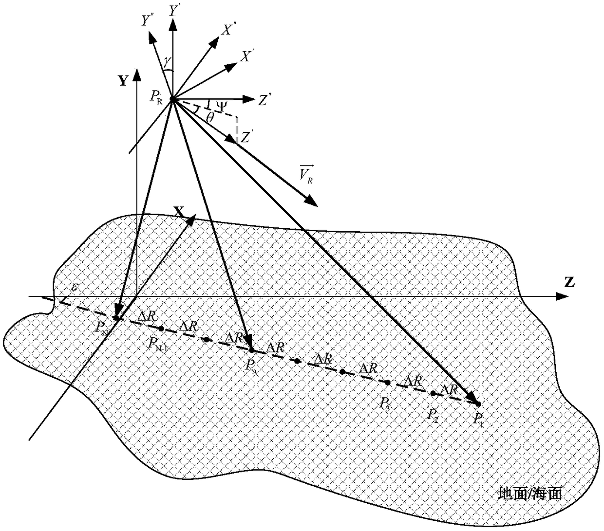
[0046] S1.1. Establish the reference coordinate system and the platform coordinate system respectively, such as figure 2 shown;

[0047] Among them, the origin of the reference coordinate system is set on the ground / sea surface, the X axis is the north direction, the Y axis is the sky direction, the Z axis is the east direction, and the position of the rad...


PUM


Abstract

The invention discloses a main-minor lobe land and sea clutter main distribution computing method comprising the following steps of: determining a main-minor lobe land and sea clutter main distribution corresponding area according to the gain of a radar bottom view stern detection wave beam in each direction; selecting corresponding clutter points in the corresponding area and computing the position coordinates of all the clutter points; computing the relative distance and relative Doppler frequencies of all the clutter points and the radar according to the position coordinates of the radar, a velocity vector parameter, and the position coordinates of all the clutter points; computing the apparent distance and the apparent Doppler frequencies of all the clutter points in combination with the maximum unambiguous distance and the pulse repetition frequency parameter of a radar transmitted signal; and quantifying the apparent distance and the apparent Doppler frequencies of all the clutter points and mapping the quantified distance and the quantified Doppler frequencies of all the clutter points onto a distance-frequency domain to obtain the accurate position of the main-minor lobe land and sea clutter main distribution. The method is good in computing instantaneity and improves radar bottom view stern detection capability and tracking performance.

Description

technical field [0001] The invention relates to the technical field of radar downsight and rearward detection, in particular to a method for calculating the main distribution of main and secondary lobe ground-sea clutter under radar downsight and rearward detection. Background technique [0002] Ground-sea clutter is the most restrictive factor for the performance of detecting and tracking targets after looking behind the radar. The air target is detected after looking down and the tail, the target echo signal falls into the sidelobe clutter area, and the repetitive frequency waveform is used to detect the target in the radar transmission. Compared with the high repetition frequency waveform, the use of the medium repetition frequency waveform can reduce the distance aliasing degree of the sidelobe clutter, and further reduce the power of the sidelobe clutter through the distance dimension cutting, so that the radar has the ability to detect the tail and tail. However, sinc...

Claims


Application Information

Patent Timeline
Patent Type & Authority Patents(China)
IPC IPC(8): G01S7/295G01S7/41
CPCG01S7/295G01S7/41
Inventor 杜科易堃谭智马超唐文明沈军郑博
Owner SHANGHAI RADIO EQUIP RES INST
Why Eureka
Eureka Blog
Learn More