Scanning wave beam high-resolution radar scatterometer

A high-resolution, radar-scattering technology, applied in the direction of reflection/re-radiation of radio waves, utilization of re-radiation, radio wave measurement systems, etc., can solve problems such as the decline of inversion accuracy

Active Publication Date: 2016-11-09
NAT SPACE SCI CENT CAS
View PDF4 Cites 13 Cited by
  • Summary
  • Abstract
  • Description
  • Claims
  • Application Information

AI Technical Summary

Problems solved by technology

However, for land observations with large diurnal changes such as freeze-thaw mon...

Method used


Image

  • Scanning wave beam high-resolution radar scatterometer
  • Scanning wave beam high-resolution radar scatterometer
  • Scanning wave beam high-resolution radar scatterometer

Examples


Embodiment Construction

[0061] The present invention will be further described in detail below in conjunction with the accompanying drawings.

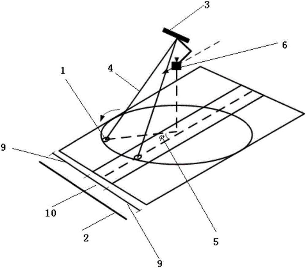
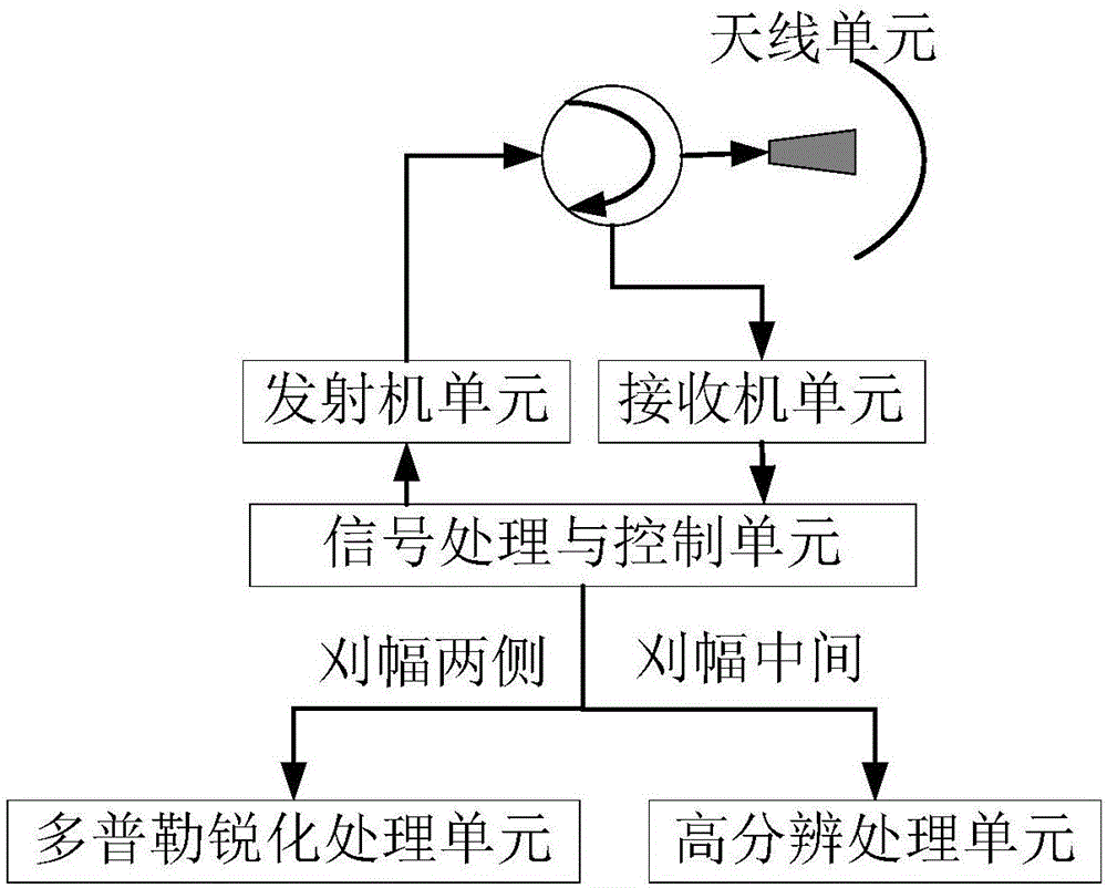
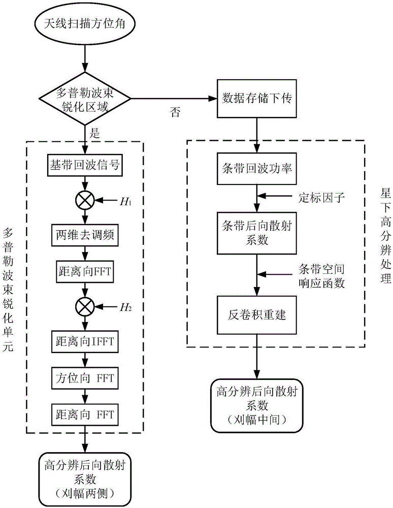
[0062] The invention provides a high-resolution radar scatterometer for scanning beams. At the same time, the invention proposes a technical solution combining beam conical scanning and high-resolution processing to meet the observation requirements of both wide swath and high resolution. The radar scatterometer uses a beam rotating scanning antenna, such as figure 2 As shown, it includes: an antenna unit, a transmitter unit, a receiver unit, a digital processing and control unit, a Doppler sharpening processing unit and a high-resolution processing unit; the antenna unit adopts a narrow beam conical scanning system for realizing Rotate the pencil beam to scan, the transmitter unit generates and transmits a chirp signal, and when transmitting the chirp signal, it corresponds to an observation azimuth The receiver unit receives the pulse signal and performs...


PUM


Abstract

The invention provides a scanning wave beam high-resolution radar scatterometer which employs a pen-shaped wave beam conical scanning system and comprises an antenna unit, a transmitter unit, a receiver unit, a signal processing and control unit, a doppler sharpening processing unit and a high resolution processing unit, wherein the antenna unit employs a narrow wave beam conical scanning system, and the transmitter unit generates linear frequency modulation pulse signals. The pulses when emitted correspond to one observation azimuth phi', and the receiver unit conducts low noise amplification, central frequency reception, mixed frequency deramping and phase demodulation processing for received pulse signals, and extracts echo signals. The digital processing and controlling unit records the observation azimuth phi' corresponding to the emitted signals, and determines the antenna oriented wave beam irradiation area of the radar scatterometer, whether on two sides of a swath or in the center of the swath, according to the magnitude of the observation azimuth phi'. Whether a doppler wave beam sharpening method or a high-sampling reconstruction method is employed is determined, and the high-resolution backward scattering coefficient is thus obtained.

Description

technical field [0001] The invention relates to the technical field of radar scatterometers, in particular to a high-resolution radar scatterometer for scanning beams. Background technique [0002] Radar scatterometer is a radar system used to measure the normalized backscatter coefficient of the earth's surface. Its original design target is applied to the measurement of large-scale ocean surface wind, that is, the measured The backscatter data are retrieved to generate the sea surface wind field. As an active microwave remote sensor, the scatterometer has the advantages of wide observation swath, fast global coverage, and high measurement accuracy, and has become an ideal sensor for land quantitative remote sensing. [0003] According to the antenna configuration and the implementation of observation azimuth angle measurement, spaceborne microwave scatterometers are divided into three types: fixed fan beam scatterometer, pencil beam rotating scanning scatterometer and fan...

Claims


Application Information

Patent Timeline
IPC IPC(8): G01S13/88G01S13/95
CPCG01S13/885G01S13/95Y02A90/10
Inventor 董晓龙刘丽玲王刚朱迪徐星欧
Owner NAT SPACE SCI CENT CAS
Why Eureka
Try Eureka