Smart monitoring method and system
An intelligent monitoring system and intelligent monitoring technology, applied in closed-circuit television systems, instruments, computer components, etc., can solve the problems of not being able to obtain target objects in real time, and achieve the effect of improving user experience and facilitating monitoring
- Summary
- Abstract
- Description
- Claims
- Application Information
AI Technical Summary
Problems solved by technology
Method used
Image
Examples
Embodiment 1
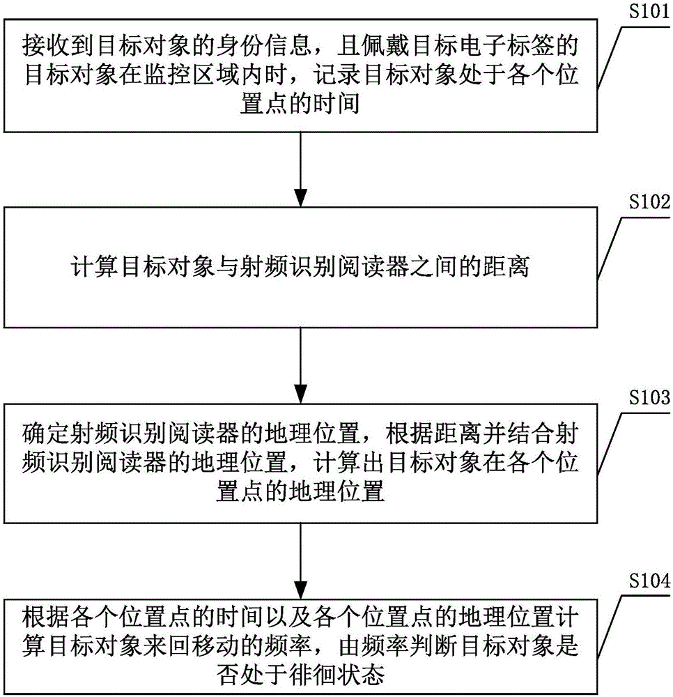
[0054] Such as figure 1 As shown, the intelligent monitoring method includes the following steps:
[0055] S101. When the identity information of the target object is received, and the target object wearing the target electronic tag moves in the monitoring area, record the time when the target object is at each position point.
[0056] Target electronic tags (Radio Frequency Identification, RFID) are composed of coupling elements and chips. Each target electronic tag has a unique electronic code. High-capacity target electronic tags have storage space for users to write, and are attached to objects to identify targets. object.
[0057]The target electronic tag is placed on the target object, and the target object can be a person, pet, object, etc. that need to be monitored. For example, target electronic tags can be fixed or worn on people and pets. The movement of the target object will drive the movement of the target electronic tag, that is, the movement of the target ob...
Embodiment 2
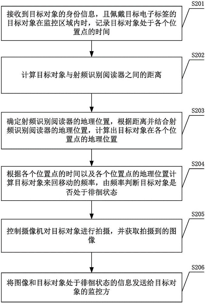
[0067] Such as figure 2 As shown, steps S201 to S204 of the intelligent monitoring method are the same as steps S101 to S104 in the first embodiment, please refer to the first embodiment of the intelligent monitoring method for details. On the basis of the first embodiment of the intelligent monitoring method, the following steps are also included:
[0068] S205. Control the camera to shoot the target object, and acquire the captured image.
[0069] When the camera receives the shooting instruction sent by the radio frequency identification server, it will shoot the target object. When shooting, the camera will automatically focus. When the target object moves in the monitoring area, the camera will rotate along with the movement of the target object, so as to be able to photograph the target object.
[0070] The camera sends the captured image to the radio frequency identification server for saving or performing other operations. The images acquired by the radio frequency...
Embodiment 3
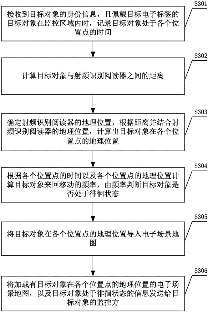
[0077] Such as image 3 As shown, steps S301 to S304 of the intelligent monitoring method are the same as steps S101 to S104 in the first embodiment, please refer to the first embodiment of the intelligent monitoring method for details. On the basis of the first embodiment of the intelligent monitoring method, the following steps are also included:
[0078] S305. Import the geographic location of the target object at each location point into the electronic scene map.
[0079] Importing the coordinates of the geographic location into the electronic scene map can more intuitively reflect the location of the target object, and it is also convenient for the monitoring party to quickly find the target object according to the electronic scene map.
[0080] S306. Send the electronic scene map loaded with the geographic location of the target object at each location point to the monitoring party of the target object.
[0081] When sending, information such as the electronic scene ma...
PUM
 Abstract
Description
Claims
Application Information
 - R&D
- Intellectual Property
- Life Sciences
- Materials
- Tech Scout
- Unparalleled Data Quality
- Higher Quality Content
- 60% Fewer Hallucinations
Browse by: Latest US Patents, China's latest patents, Technical Efficacy Thesaurus, Application Domain, Technology Topic, Popular Technical Reports.
© 2025 PatSnap. All rights reserved.Legal|Privacy policy|Modern Slavery Act Transparency Statement|Sitemap|About US| Contact US: help@patsnap.com


