Rotor for motor and motor with rotor

A technology of rotor and rotor core, which is applied in the direction of electrical components, electromechanical devices, electric components, etc., can solve the problems of smaller permanent magnet placement space and low magnetic concentration efficiency of permanent magnets, and achieve excellent air gap magnetic field distribution. Gap flux density, the effect of improving motor performance

Active Publication Date: 2016-11-09
GUANGDONG WELLING ELECTRIC MACHINE MFG +1
View PDF7 Cites 10 Cited by
  • Summary
  • Abstract
  • Description
  • Claims
  • Application Information

AI Technical Summary

Problems solved by technology

[0002] At present, motors such as permanent magnet brushless motors for air-conditioning fans mostly use surface-mounted magnetic tile rotor structures. In order to meet the energy efficiency requirements of the motor, the axial length of the permanent magnet is usually increased, and the air gap is increased by using the magnetic field concentration effect. Magnetic flux density, thus improving efficiency, however, permanent magnets have low magnetic flux gathering efficiency
[0003] The motor in the prior art adopts a built-in magnetic tile rotor structure to improve the magnetic gathering ability. However, in this structure, the outer peripheral surface of the rotor iron core adopts a three-section arc cutting method to form an uneven air gap to reduce the air gap magnetic field. Optimize so that after arc cutting, the placement position of the permanent magnet is compressed inward, and the placement space of the permanent magnet becomes smaller

Method used


Image

  • Rotor for motor and motor with rotor
  • Rotor for motor and motor with rotor

Examples


Embodiment Construction

[0030] Embodiments of the present invention are described in detail below, examples of which are shown in the drawings, wherein the same or similar reference numerals designate the same or similar elements or elements having the same or similar functions throughout. The embodiments described below by referring to the figures are exemplary only for explaining the present invention and should not be construed as limiting the present invention.

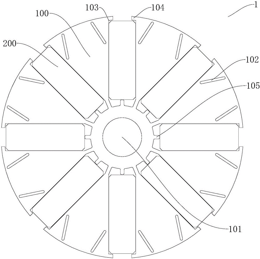
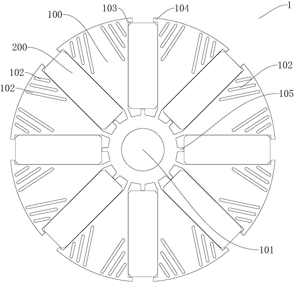
[0031] Refer below figure 1 and figure 2 Describe the rotor 1 for a motor according to the embodiment of the first aspect of the present invention. The rotor 1 for a motor is suitable for a permanent magnet brushless motor with built-in magnetic tiles, which can improve the magnetic gathering ability and improve the air gap magnetic field without reducing the Placement space for small permanent magnets.

[0032] Such as figure 1 and figure 2 As shown, the rotor 1 for a motor according to the embodiment of the present invention incl...


PUM


Abstract

The invention discloses a rotor for a motor and the motor with the rotor. The rotor for the motor comprises a rotor core and a plurality of permanent magnets, wherein the rotor core comprises a rotating shaft hole; the rotor core is provided with a slit which runs through the rotor core along the axial direction of the rotor core and the slit and the peripheral surface of the rotor core are arranged at an interval; the permanent magnets are internally arranged in the rotor core; in the cross section of the rotor core, each permanent magnet extends along the radial direction of the rotor core; the plurality of permanent magnets are arranged along the circumferential direction of the rotor core; and the homopolarity of the adjacent permanent magnets in the circumferential direction of the rotor core is opposite. According to the rotor for the motor, the magnetic concentrating capability can be improved; the air-gap field is improved; and the placement space for the permanent magnets is not reduced.

Description

technical field [0001] The invention relates to the technical field of motor manufacturing, in particular to a rotor for a motor and a motor with the rotor for a motor. Background technique [0002] At present, motors such as permanent magnet brushless motors for air-conditioning fans mostly use surface-mounted magnetic tile rotor structures. In order to meet the energy efficiency requirements of the motor, the axial length of the permanent magnet is usually increased, and the air gap is increased by using the magnetic field concentration effect. Magnetic density, thereby improving efficiency, however, the magnetic efficiency of permanent magnets is low. [0003] The motor in the prior art adopts a built-in magnetic tile rotor structure to improve the magnetic gathering ability. However, in this structure, the outer peripheral surface of the rotor iron core adopts a three-section arc cutting method to form an uneven air gap to reduce the air gap magnetic field. Optimization...

Claims


Application Information

Patent Timeline
Patent Type & Authority Applications(China)
IPC IPC(8): H02K1/27
CPCH02K1/2746
Inventor 朱嘉东王飞陈金涛
Owner GUANGDONG WELLING ELECTRIC MACHINE MFG
Why Eureka
Try Eureka