
Permanent magnet synchronous motor with hybrid magnetic circuit arrangement

A permanent magnet synchronous motor and magnetic circuit technology, applied in synchronous motors with stationary armatures and rotating magnets, magnetic circuit rotating parts, magnetic circuit shape/style/structure, etc., to improve controllable performance and easy production , Controllable effect of magnetic focusing pole arc

Pending Publication Date: 2015-12-23
CHANGZHOU PUSHI AUTOMOTIVE POWER SYST CO LTD
View PDF1 Cites 9 Cited by
  • Summary
  • Abstract
  • Description
  • Claims
  • Application Information

AI Technical Summary

Problems solved by technology

[0006] The purpose of the present invention is to: aim at the above-mentioned technical problems existing in the prior art, provide a kind of magnetic motor that is proposed under the special performance requirements of the drive motor, and solves the problems of high power density, wide speed range, cost and electromagnetic noise of the motor. permanent magnet synchronous motor

Method used


Image

  • Permanent magnet synchronous motor with hybrid magnetic circuit arrangement
  • Permanent magnet synchronous motor with hybrid magnetic circuit arrangement
  • Permanent magnet synchronous motor with hybrid magnetic circuit arrangement

Examples


Embodiment Construction

[0032] All features disclosed in this specification, or steps in all methods or processes disclosed, may be combined in any manner, except for mutually exclusive features and / or steps.

[0033] Any feature disclosed in this specification (including any appended claims, abstract and drawings), unless expressly stated otherwise, may be replaced by alternative features which are equivalent or serve a similar purpose. That is, unless expressly stated otherwise, each feature is one example only of a series of equivalent or similar features.

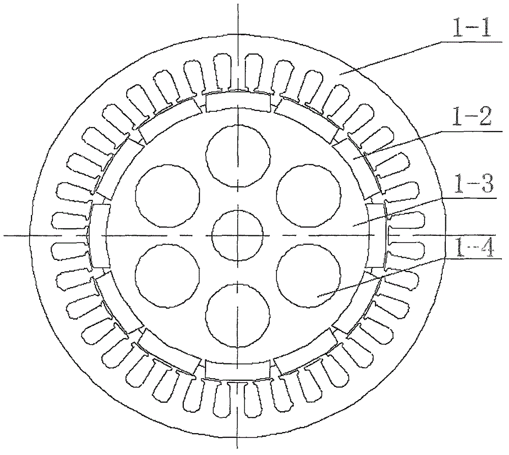
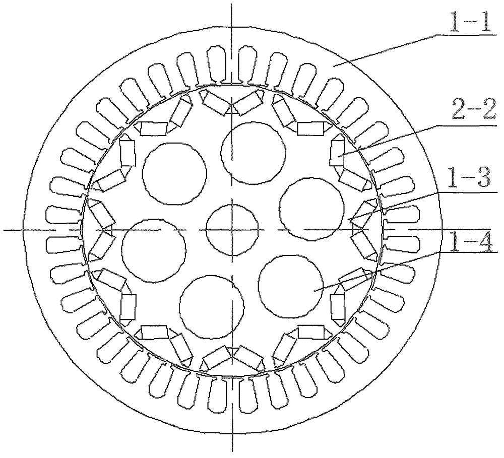
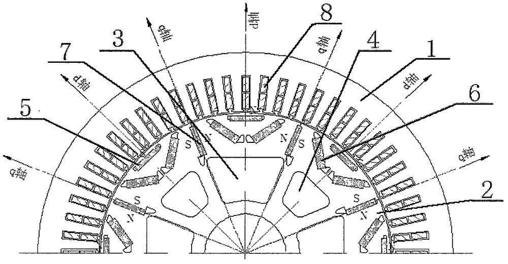
[0034] Specific examples, such as image 3 and 4 As shown, a permanent magnet synchronous motor with a mixed arrangement of magnetic circuits includes a stator core 1 and a rotor, the stator core 1 is embedded with an armature winding 8, and the rotor includes a rotor core 2 and a rotor embedded in the rotor The magnetic steel on the iron core 2, wherein: the magnetic steel is non-uniformly arranged at the circumferential edge of the rotor c...


PUM


Abstract

The present invention relates to a permanent magnet synchronous motor with hybrid magnetic circuit arrangement. The permanent magnet synchronous motor with the hybrid magnetic circuit arrangement comprises a stator iron core (1) and magnetic steels, the magnetic steels are arranged at the circumferential edge of a rotor iron core (2) unevenly, and comprise the tangential magnetic steels (7), the linear magnetic steels (5) and the V-shaped magnetic steels (6). Each V-shaped magnetic steel (6) is formed by arranging two magnetic steels, and the linear magnetic steels (5) are located at the inner side of a V-shaped magnetic steel set (6) and are close to the circumferential edge of the rotor iron core (2). The tangential magnetic steels (7) are arranged on a q-axis of the motor, and the number of the tangential magnetic steels (7) and the linear magnetic steels (5) is equal to the number of the V-shaped magnetic steels (6) and is equal to the series of the motor. The inner side of the rotor iron core (2) is equipped with the de-weight holes having the same number with the series of the motor, and the de-weight holes comprise the large de-weight holes (3) and the small de-weight holes (4). The permanent magnet synchronous motor with the hybrid magnetic circuit arrangement of the present invention solves the problems of the motor of high power density and cost, wide speed regulation range and electromagnetic noise.

Description

technical field [0001] The invention relates to the technical field of motors, in particular to a permanent magnet synchronous motor with mixed magnetic circuits. Background technique [0002] In recent years, with the rise of the new energy vehicle industry, the vehicle drive motor has higher and higher requirements on the peak torque and speed range of the motor. In order to meet the size of the vehicle and reduce the system cost, the system hopes that the motor has a larger reluctance torque share. . According to the survey: At present, the proportion of the salient pole reluctance torque of the motor developed by major motor companies at home and abroad and the torque generated by the permanent magnet steel are generally less than 45%. If the ratio can be further increased, the system cost can be effectively reduced and the motor power can be improved. Performance and system matching. In the hybrid vehicle system, the space is tight, and the requirements for the power ...

Claims


Application Information

Patent Timeline
Patent Type & Authority Applications(China)
IPC IPC(8): H02K21/14H02K1/27
Inventor 沈阳
Owner CHANGZHOU PUSHI AUTOMOTIVE POWER SYST CO LTD
Learn More