Method for determining passivation quality of PERC battery back passivation film layer
A back passivation and passivation film technology, applied in circuits, electrical components, photovoltaic power generation, etc., can solve the problems of expensive testing equipment, only single-chip analysis but not batch analysis, so as to achieve no investment in fixed equipment and avoid batch abnormality. , the effect of improving the yield
- Summary
- Abstract
- Description
- Claims
- Application Information
AI Technical Summary
Problems solved by technology
Method used
Image
Examples
Embodiment 1
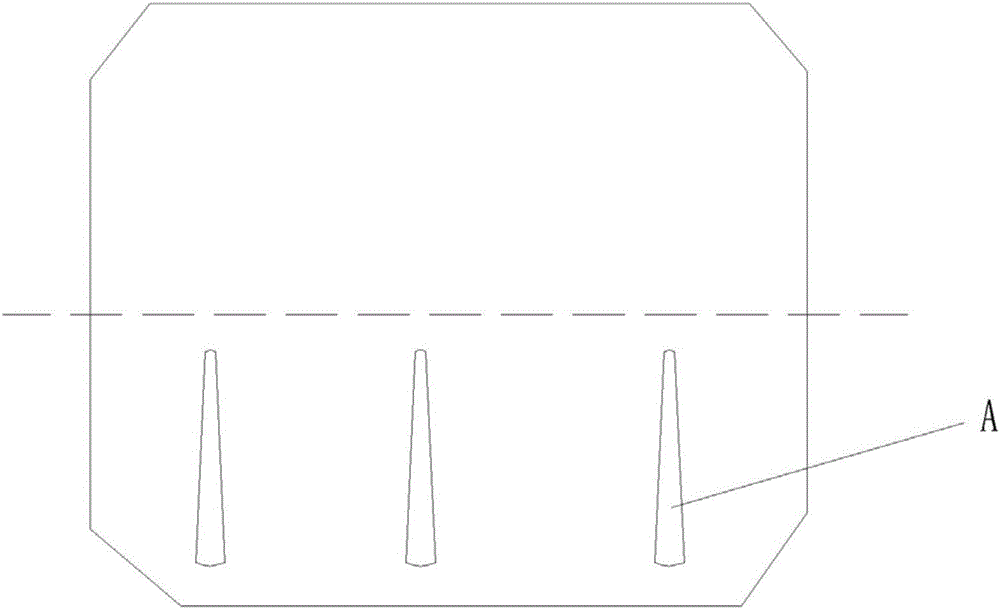
[0026] AlO on the backside after PECVD plating x / SiN y Put the semi-finished PERC battery with passivation film into 4% HF solution by volume. The appearance and color of the semi-finished battery look completely normal. Expose half of the semi-finished battery to the air, and immerse the other half in the HF solution. The surface state of the silicon wafer in the battery changes, and when the reaction reaches 7 minutes, a "strip" color difference appears in the local area of the surface of the battery semi-finished product (such as figure 1 The area A shown, below the dotted line is the area immersed in the HF solution), showing that the corrosion rate in the local area is too fast, and the corrosion rate in the local area is very slow, indicating that AlO x / SiN y The density of the passivation film varies greatly, although the appearance of the entire surface before corrosion looks the same, it is necessary to check the AlO x During the deposition process, whether th...
Embodiment 2
[0028] AlO on the backside after PECVD plating x / SiN y The semi-finished PERC battery with a passivation film layer is placed in a 4% HF solution by volume. Half of the semi-finished battery is exposed to the air and half is immersed in the HF solution. Observe the changes in the surface state of the silicon wafer immersed in the HF solution. At 4 minutes, a white "floc" appeared on the surface of the semi-finished battery, and the "floc" was a small piece of AlO that fell off. x / SiN y passivation layer, due to the AlO x / SiN y The density of the passivation film layer is poor, and the passivation film layer was corroded by HF in the HF solution and fell off, and the surface of the semi-finished product was completely dehydrated when it was corroded for 5 minutes, indicating that AlO x / SiN y The film density is very poor.
Embodiment 3
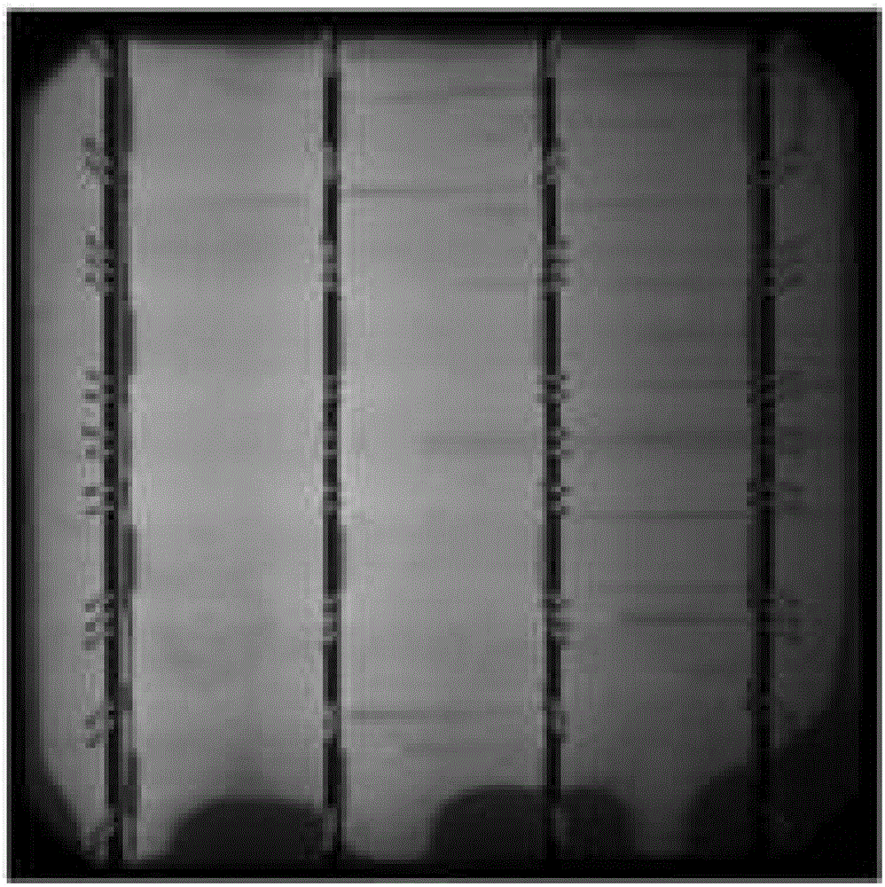
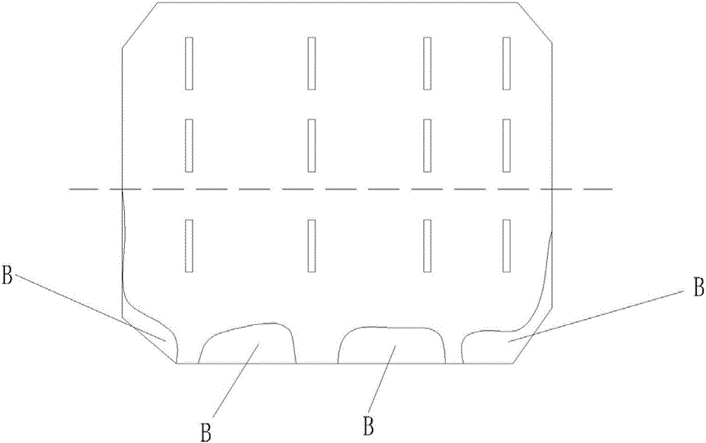
[0030] Will look normal but have black speckled shadows under the EL (eg figure 2 Shown) the finished battery corrodes the front and back electrodes, and corrodes the back film with 8% HF solution by volume. image 3In the area B shown, below the dotted line is the area immersed in the HF solution), the appearance of the shadow of the black spot changes after 3 minutes of corrosion, and it is completely dehydrated after 5 minutes of corrosion. The coating on the black spot is abnormal, and the coating process problem needs to be checked.
PUM
 Abstract
Description
Claims
Application Information
 - R&D
- Intellectual Property
- Life Sciences
- Materials
- Tech Scout
- Unparalleled Data Quality
- Higher Quality Content
- 60% Fewer Hallucinations
Browse by: Latest US Patents, China's latest patents, Technical Efficacy Thesaurus, Application Domain, Technology Topic, Popular Technical Reports.
© 2025 PatSnap. All rights reserved.Legal|Privacy policy|Modern Slavery Act Transparency Statement|Sitemap|About US| Contact US: help@patsnap.com


