
Optical lens center thickness measuring instrument

A center thickness, optical lens technology, applied in the field of measuring instruments, can solve problems such as lens damage, clamping limit, etc., to achieve the effect of improving accuracy and accuracy

Inactive Publication Date: 2022-07-29
上饶市光耀光学设备制造有限公司
View PDF1 Cites 0 Cited by
  • Summary
  • Abstract
  • Description
  • Claims
  • Application Information

AI Technical Summary

Problems solved by technology

[0005] In order to overcome the disadvantages of the above-mentioned patents that the lens cannot be clamped and limited during lens measurement, and the lens is easily damaged, the technical problem of the present invention is: to provide a lens that can be clamped and limited during lens measurement, Optical lens center thickness measuring instrument that prevents lens damage

Method used


Image

  • Optical lens center thickness measuring instrument
  • Optical lens center thickness measuring instrument
  • Optical lens center thickness measuring instrument

Examples


Embodiment 1

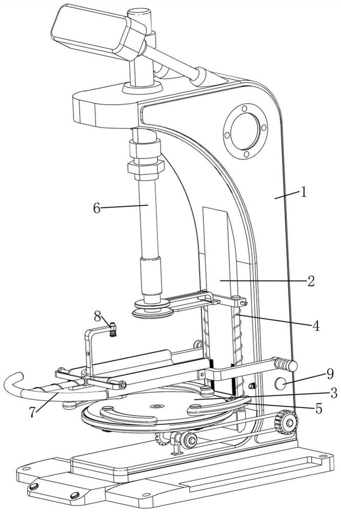
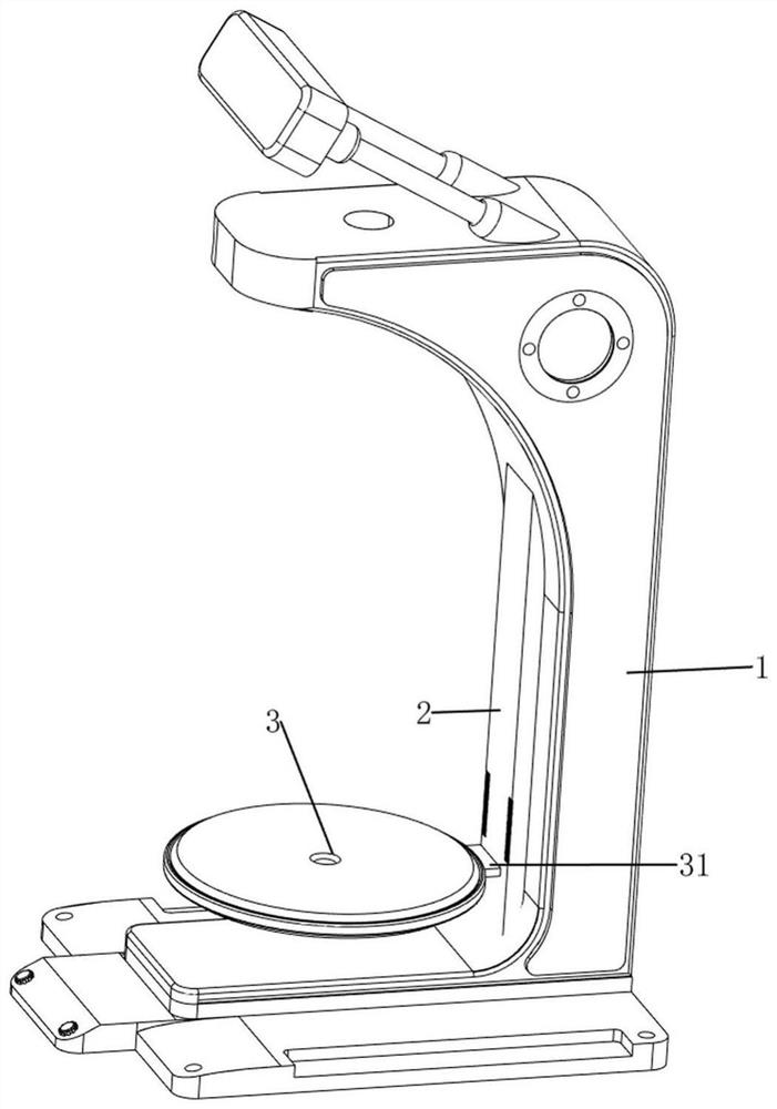
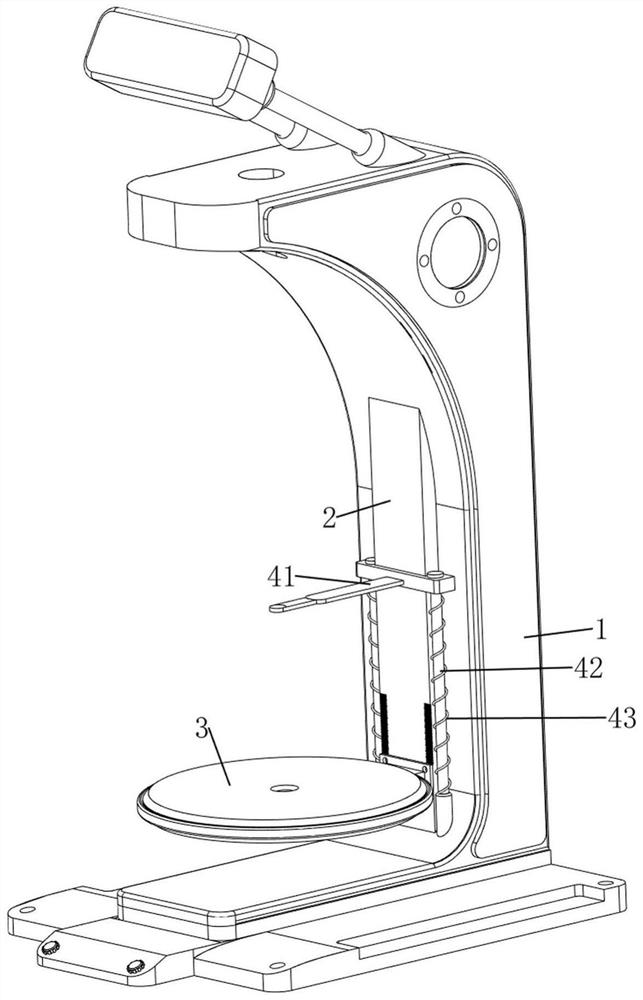
[0031] An optical lens center thickness measuring instrument, such as Figure 1-5 As shown, it includes a base 1, a ruler 2, a feeding plate 3, a first sliding sleeve 31, a measuring mechanism 4 and a clamping mechanism 5. A ruler 2 is provided on the front side of the base 1, and the ruler 2 can measure the lens. The ruler 2 The lower part of the front side is provided with a first sliding sleeve 31, the upper side of the first sliding sleeve 31 is provided with a feeding plate 3, the feeding plate 3 can be used to place the lens, the ruler 2 is provided with a measuring mechanism 4, and the measuring mechanism 4 can make the lens The measurement result is more accurate. The unloading plate 3 is provided with a clamping mechanism 5, and the clamping mechanism 5 can clamp and limit the lens.

[0032] like figure 1 and image 3 As shown, the measuring mechanism 4 includes a lower pressing plate 41, a first sliding rail 42 and a first spring 43, the ruler 2 is slidably connect...

Embodiment 2

[0036] On the basis of Example 1, as figure 1 and Image 6 As shown, it also includes a pressing mechanism 6 that can automatically measure the thickness of the lens. The pressing mechanism 6 includes a cylinder 61, a pressing plate 62 and a pressing portion 63. The upper part of the base 1 is provided with a cylinder 61, and the cylinder 61 is a telescopic rod. There is a pressing part 63 on the top, the extension of the telescopic rod of the cylinder 61 can make the pressing part 63 move downward, the rear side of the pressing part 63 is connected with the upper side of the pressing plate 41, and a pressing plate is arranged on the lower side of the pressing part 63 62. The pressing plate 62 is made of rubber, and the rear side of the pressing plate 62 is connected with the front side of the lower pressing plate 41.

[0037] When people need to measure the thickness of the center of the lens, first, people place the lens on the center position of the feeding plate 3, and th...


PUM


Abstract

The invention relates to a measuring instrument, in particular to an optical lens center thickness measuring instrument. The technical problem of the invention is to provide the optical lens center thickness measuring instrument which can clamp and limit a lens during measurement so as to prevent the lens from being damaged. According to the technical scheme, the optical lens center thickness measuring instrument comprises a base, a scaleplate, a discharging plate, a first sliding sleeve and the like, the scaleplate is arranged on the front side of the base, and the first sliding sleeve is arranged on the lower portion of the front side of the scaleplate. A lens is placed on a discharging plate, then a rotating part is rotated, a second gear and a first gear are made to rotate, then a clamping part is made to rotate towards the inner side, the lens can be clamped and limited, then people move a lower pressing plate towards the lower side, and when the lower pressing plate makes contact with the center position of the lens, the lens is clamped and limited. People can judge the thickness of the center of the lens by observing the unshielded part at the lower part of the scale.

Description

technical field [0001] The invention relates to a measuring instrument, in particular to a measuring instrument for the center thickness of an optical lens. Background technique [0002] In the field of optics, the three basic parameters of optical lenses are the central thickness, refractive index and radius of curvature. The error in the processing of the central thickness of the optical lens is an important factor affecting the imaging of the optical system. Therefore, the optical lens needs to be adjusted before it is put into the market. Center thickness is measured. [0003] Application publication number CN110132099A discloses an optical lens center thickness measuring instrument, which includes a base, a workbench is set on the base, a column is also set on the base, a measuring mechanism is set on the column, and a positioning seat is set on the workbench, A correction block is arranged on the positioning seat. A accommodating cavity for accommodating the correcti...

Claims


Application Information

Patent Timeline
Patent Type & Authority Applications(China)
IPC IPC(8): G01B5/06
CPCG01B5/06
Inventor 杨昔志黄金枝
Owner 上饶市光耀光学设备制造有限公司
Learn More