
Bridge pier erosion and deposition safety monitoring system

A technology for safety monitoring and bridge piers, applied in measurement devices, instruments, climate change adaptation, etc., can solve problems such as hidden safety hazards, power impact, and inability to observe intuitively, and achieve reduced safety hazards, accurate sediment thickness, and accurate monitoring results. Effect

Active Publication Date: 2021-05-07
SECOND INST OF OCEANOGRAPHY MNR
View PDF5 Cites 0 Cited by
  • Summary
  • Abstract
  • Description
  • Claims
  • Application Information

AI Technical Summary

Problems solved by technology

[0003] At present, the erosion and deposition of channel sediment mainly uses multi-beam and other acoustic measurement techniques to scan the river bed elevation to obtain the river bottom elevation, and compare and analyze the measurement results in different periods to obtain the sediment erosion and deposition situation in the measured river section. The sediment erosion and silting measurement method is limited by the cost of a single scan and cannot achieve real-time or multi-frequency measurement. The monitoring of the sediment scouring and silting thickness is highly dependent on data and cannot be observed intuitively, making it difficult for staff to observe in real time The general situation of the sediment, and when a large amount of natural rain comes, it will usually affect the power. In this case, the thickness of the silted sediment cannot be grasped in time, and there is a large safety hazard

Method used


Image

  • Bridge pier erosion and deposition safety monitoring system
  • Bridge pier erosion and deposition safety monitoring system
  • Bridge pier erosion and deposition safety monitoring system

Examples


Embodiment 1

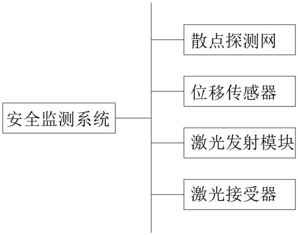
[0038] see figure 1 , a bridge pier erosion and silting safety monitoring system, including a monitoring center, multiple displacement sensors, multiple laser emitters, multiple laser receivers and two scattered detection networks, displacement sensors, laser transmitters, and laser receivers are all connected to The monitoring center signal is connected, and two scattered detection networks are respectively installed at the corresponding positions of the two bridge piers.

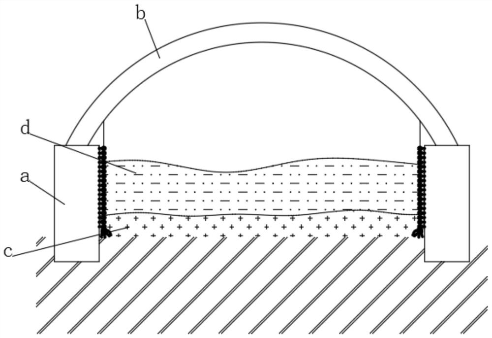
[0039] see Figure 2-3 , in the figure, a represents the bridge pier, b represents the bridge, c represents the deposited sediment, and d represents the water flow. The upper end of the scatter detection network is fixedly connected with a positioning rope 2, and the positioning rope 2 is fixedly connected with the inner top of the bridge. The scatter detection network includes multiple A photosensitive ball point, a self-extending rope 4 is fixedly connected between two adjacent photosensitive ball point...


PUM


Abstract

The invention discloses a bridge pier erosion and deposition safety monitoring system, and belongs to the field of bridge pier monitoring. The bridge pier erosion and deposition safety monitoring system is characterized in that through arrangement of a scattered point detection net, along with the more and more sediment deposition amount, the pressure borne by light sensing ball points at the bottom is gradually increased, the density of the light sensing ball points is gradually reduced. the density of the generated light spots becomes smaller and smaller, and the thickness of sediment deposition becomes larger and larger, so that the situation of sediment erosion and deposition is visually and preliminarily judged according to the density of the light spots, the dependence on data is reduced, the situation of sediment deposition is effectively prevented from being judged under the condition of power failure, and potential safety hazards are reduced; and the effect of accurately judging the sediment thickness can be achieved according to the light receiving condition of the laser receiver, and each light sensing ball point is fixed to the bridge pier, so that the stability of the scattered point detection net is higher, the monitoring result is not prone to being affected, and the accuracy of the monitoring result is higher.

Description

technical field [0001] The invention relates to the field of bridge pier monitoring, in particular to a bridge pier erosion and silting safety monitoring system. Background technique [0002] During the operation and maintenance of the channel, the waterway will face the problem of sediment deposition in the channel, which will reduce the scale of the channel and affect the navigation guarantee rate of the channel. At the same time, sediment erosion and sedimentation may also occur near the waterway regulation buildings built in the waterway, causing water damage and failure of the waterway regulation buildings, affecting the safety and smoothness of the waterway, so real-time monitoring of sediment erosion It is of great significance to ensure the scale of the channel and the smoothness of the channel. But at present, there is no real-time monitoring technology and system for waterway sediment filling and silting in China. [0003] At present, the erosion and deposition o...

Claims


Application Information

Patent Timeline
Patent Type & Authority Applications(China)
IPC IPC(8): G01B11/06
CPCG01B11/06Y02A30/30
Inventor 谢中宇张俊彪俞亮亮宋泽坤徐却飞鲍鹏飞许雪峰
Owner SECOND INST OF OCEANOGRAPHY MNR
Learn More