Induction indication point light source and passage indication board

A technology of indicating points and light sources, which is applied in the field of traffic signs and induction indicating point light sources, can solve problems such as waste of electric energy, and achieve the effects of avoiding waste of electric energy, excellent performance, and low cost

Inactive Publication Date: 2016-11-09
张远海
View PDF4 Cites 1 Cited by
  • Summary
  • Abstract
  • Description
  • Claims
  • Application Information

AI Technical Summary

Problems solved by technology

[0002] At night, in some road sections where construction or accidents occur, luminous signs are often used to remind oncoming vehicles to pay attention to avoiding. The signs with the same function are also used for traffic guidance in indoor stadiums. The light sources on such signs are always on. , in the case of idle (no object approaching), it will cause waste of electric energy
The most ideal situation is that when a vehicle or human body is detected approaching, the light source on the sign will be turned on for traffic guidance, and the light source will be turned off when it is idle; the technical problem faced is that when the vehicle approaches at high speed How to turn on the light source in time for warning

Method used


Image

  • Induction indication point light source and passage indication board
  • Induction indication point light source and passage indication board
  • Induction indication point light source and passage indication board

Examples


Embodiment Construction

[0014] The scheme of this application is further described in conjunction with the accompanying drawings as follows:

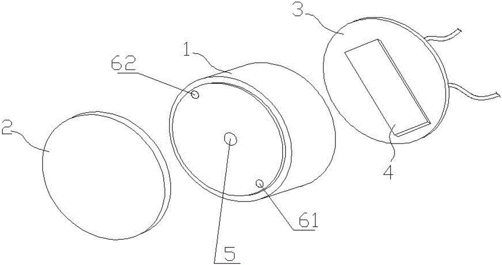
[0015] like figure 1 and 2 As shown, the induction indicating point light source of the present invention includes a housing 1, a mask 2 arranged on the front of the housing 1, and a bottom cover 3 arranged on the back of the housing 1, the mask 2 is transparent or translucent, and the mask 2 A light source 5 is provided on the front side of the opposite housing 1, and a control circuit 4 and a microwave radar 6 are provided in the cavity enclosed by the housing 1 and the bottom cover 3. The microwave radar has a transmitter 61 and a receiver facing the front of the point light source. 62.

[0016] The light source 5 is an LED light source assembly.

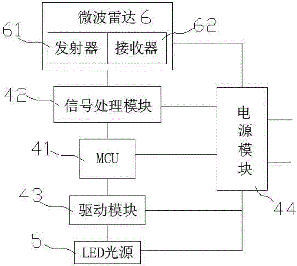
[0017] The control circuit 4 includes an MCU 41, a signal processing module 42, a driver module 43 and a power supply module 44, the signal processing module 42 is connected to the microwave radar 6, and the d...


PUM


Abstract

The present invention provides an induction indication point light source. The induction indication point light source comprises a shell, a face mask arranged at the front surface of the shell, and a bottom cover arranged at the back surface of the shell. The face mask is transparent or semitransparent. The front surface of the shell is provided with a light source directly facing the face mask. The induction indication point light source of the invention is characterized in that a control circuit and a microwave radar are arranged in an inner cavity enclosed by the shell and the bottom cover; and the microwave radar is provided with a transmitter and a receiver which face the front direction of the point light source. The invention also provides a passage indication board using the induction indication point light source. According to the induction indication point light source and the passage indication board of the invention, a remote sensing technology is adopted, so that the light source can be turned on when a vehicle approaches the point light source, and the light source can be turned off when the vehicle goes away from the light source, and therefore, incoming vehicles can be prompted to avoid a certain construction road section, and the waste of electric energy under an idle condition can be avoided; and the indication board having same function as the induction indication point light source can be applied to passage guidance in indoor places. The induction indication point light source of the invention has the advantages of simple structure, low cost, environmental friendliness and energy-saving performance, and is particularly suitable for being used in road sections where vehicles are driven at night, and is excellent in practicality and economy both.

Description

technical field [0001] The invention relates to a light source for traffic indication, in particular to an induction point light source and a traffic sign using the point light source. Background technique [0002] At night, in some road sections where construction or accidents occur, luminous signs are often used to remind oncoming vehicles to pay attention to avoiding. The signs with the same function are also used for traffic guidance in indoor stadiums. The light sources on such signs are always on. , in the case of idle (no object approaching), it will cause a waste of electric energy. The most ideal situation is that when a vehicle or human body is detected approaching, the light source on the sign will be turned on for traffic guidance, and the light source will be turned off when it is idle; the technical problem faced is that when the vehicle approaches at high speed How to turn on the light source in time for warning. Contents of the invention [0003] Based on...

Claims


Application Information

Patent Timeline
Patent Type & Authority Applications(China)
IPC IPC(8): H05B37/02H05B33/08G09F13/22H05B44/00H05B45/10H05B45/30
CPCG09F13/22G09F2013/222H05B45/00H05B47/10
Inventor 张远海翁佩纯胡智君张晟轩
Owner 张远海
Why Eureka
Try Eureka