
fuel cell system

A fuel cell system and fuel cell technology, applied in fuel cells, power system fuel cells, circuits, etc., can solve problems such as power generation performance degradation

Active Publication Date: 2018-08-28
NISSAN MOTOR CO LTD
View PDF1 Cites 0 Cited by
  • Summary
  • Abstract
  • Description
  • Claims
  • Application Information

AI Technical Summary

Problems solved by technology

[0002] In fuel cells, when the wetness of the electrolyte membrane becomes too high or too low, power generation performance decreases

Method used


Image

  • fuel cell system
  • fuel cell system
  • fuel cell system

Examples


Embodiment Construction

[0027] Hereinafter, embodiments of the present invention will be described with reference to the drawings and the like.

[0028] A fuel cell is composed of a negative electrode serving as a fuel electrode, a positive electrode serving as an oxidant electrode, and an electrolyte membrane disposed between these electrodes. The fuel cell generates electricity using an anode gas containing hydrogen supplied to the anode electrode and a cathode gas containing oxygen supplied to the anode electrode. The electrode reactions performed at the two electrodes of the negative electrode and the positive electrode are as follows.

[0029] Negative electrode: 2H 2 →4H + +4e - …(1)

[0030] Positive electrode: 4H + +4e - +O 2 →2H 2 O...(2)

[0031] Through the electrode reactions (1) and (2), the fuel cell generates an electromotive force of about 1 V (volt).

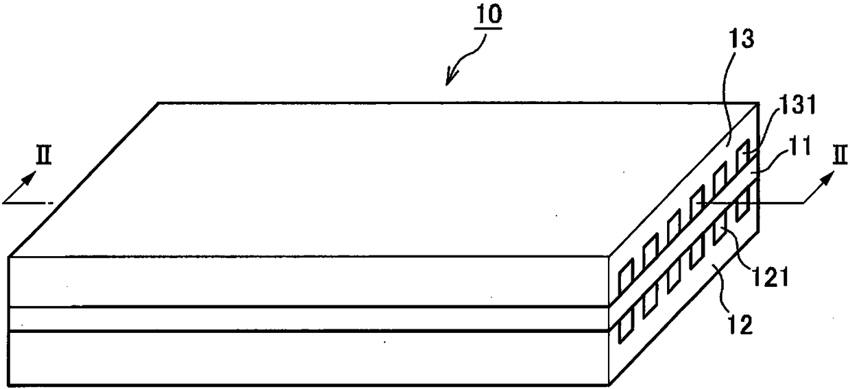
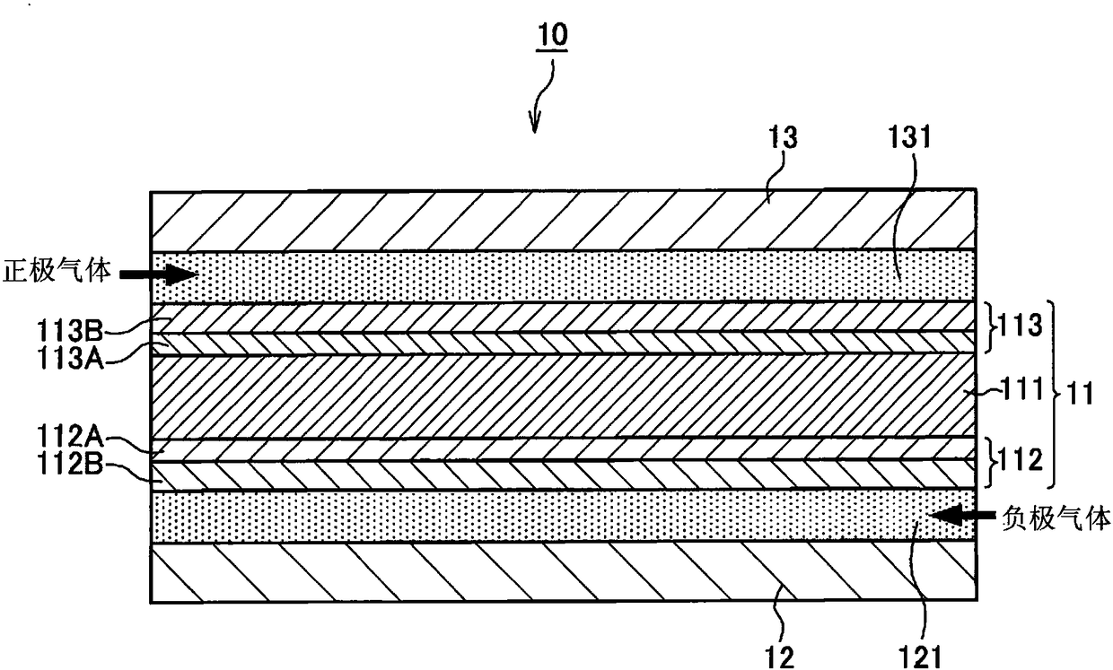
[0032] figure 1 and figure 2 It is a figure for explaining the structure of the fuel cell 10 which concerns on one Embo...


PUM


Abstract

A fuel cell system includes: a wetness target value calculating unit configured to calculate a target value of a wet state of the fuel cell; a gas required flow rate calculating unit configured to calculate a cathode gas required flow rate on the basis of a power generation request to the fuel cell; a wetness-control anode gas flow rate calculating unit configured to calculate a wetness-control anode gas circulation flow rate at least on the basis of the wetness target value and the cathode gas required flow rate during a dry control; an anode gas flow rate control unit configured to control an anode gas circulation flow rate on the basis of the wetness-control anode gas circulation flow rate; a wetness-control cathode gas flow rate calculating unit configured to calculate a wetness-control cathode gas flow rate at least on the basis of the wetness target value and a measured value or estimated value of the anode gas circulation flow rate during the dry control; and a cathode gas flow rate control unit configured to control a cathode gas flow rate on the basis of the cathode gas required flow rate and the wetness-control cathode gas flow rate.

Description

technical field [0001] The present invention relates to a fuel cell system including a fuel cell that receives supply of an anode gas and a cathode gas to generate electricity. Background technique [0002] In a fuel cell, when the wetness of the electrolyte membrane becomes too high or too low, power generation performance decreases. In order for a fuel cell to efficiently generate electricity, it is important to maintain an appropriate humidity of the electrolyte membrane of the fuel cell. [0003] JP 2010-538415 A discloses a fuel cell system that adjusts the humidity of the fuel cell by controlling at least one of the anode gas flow rate and the cathode gas flow rate. Contents of the invention [0004] The above-mentioned publication only discloses that the humidity of the fuel cell can be adjusted by controlling the flow rate of the anode gas and the flow rate of the cathode gas, but does not disclose the appropriate adjustment of the humidity based on the flow contr...

Claims


Application Information

Patent Timeline
Patent Type & Authority Patents(China)
IPC IPC(8): H01M8/04828H01M8/04089H01M8/0438H01M8/04492H01M8/04537H01M8/04746
CPCH01M8/04097H01M8/04388H01M8/04529H01M8/04619H01M8/04753H01M8/0485H01M2008/1095H01M2250/20Y02E60/50Y02T90/40H01M8/04231H01M8/04395
Inventor 青木哲也垣内孝宏藤井隆宏
Owner NISSAN MOTOR CO LTD
Learn More