
Sealing head forming mold with replaceable draw beads

A technology for forming molds and drawbeads, which is applied in the field of stamping dies, can solve the problems of increasing mold repair time, inability to provide drawbead resistance, and increasing production costs, so as to reduce the time for mold installation and mold testing, and solve the problem of inability to disassemble The effect of replacing the drawbead and prolonging the service life

Inactive Publication Date: 2016-11-16
HEFEI UNIV OF TECH
View PDF5 Cites 0 Cited by
  • Summary
  • Abstract
  • Description
  • Claims
  • Application Information

AI Technical Summary

Problems solved by technology

The early stamping forming was realized by the step-by-step forming of multiple molds. Although the step-by-step forming can realize the stamping and forming of the head, it has the disadvantages of cumbersome procedures, high production costs, and is not conducive to mass production; with the development of stamping technology, in The introduction of drawbeads in the head forming has realized the one-step cold stamping of the head, which is improved compared with the step-by-step forming, but there is still a single mold that can only produce one type of head, which has high production costs, low production efficiency, and scrap rate. high disadvantage
In the current head forming mold, the ribs of the drawbead are usually fixed on the binder plate or the die, but this kind of drawbead fixed mold cannot provide different drawbead resistance, and the mold can only be used for plates of the same thickness. Processing and forming
Using the same mold to process heads with different material thicknesses requires different drawbead resistances, while drawbead fixed molds cannot provide different drawbead resistances
In addition, this type of fixed drawbead mold is inconvenient to repair the mold, which may cause the die to be scrapped because the drawbead cannot be repaired, thus increasing the repair time of the mold and reducing the service life and production efficiency of the mold. thereby increasing production costs

Method used


Image

  • Sealing head forming mold with replaceable draw beads
  • Sealing head forming mold with replaceable draw beads
  • Sealing head forming mold with replaceable draw beads

Examples


Embodiment Construction

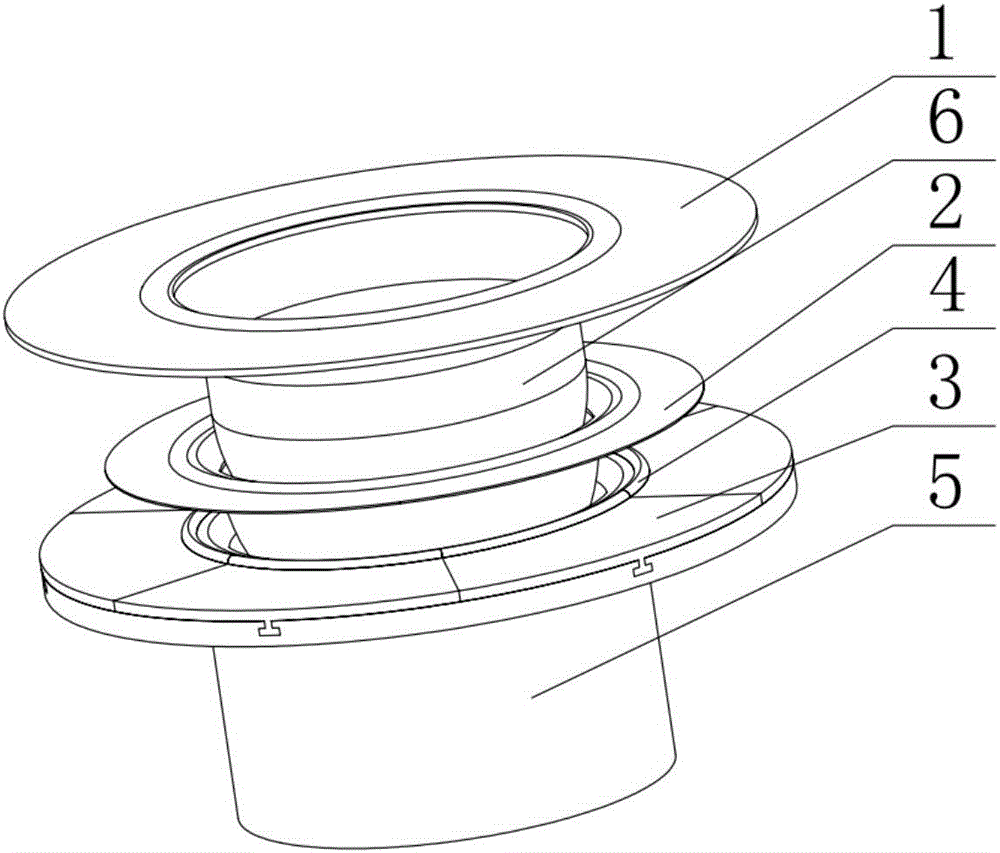
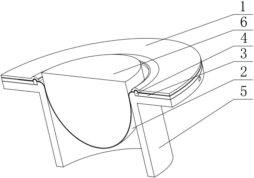
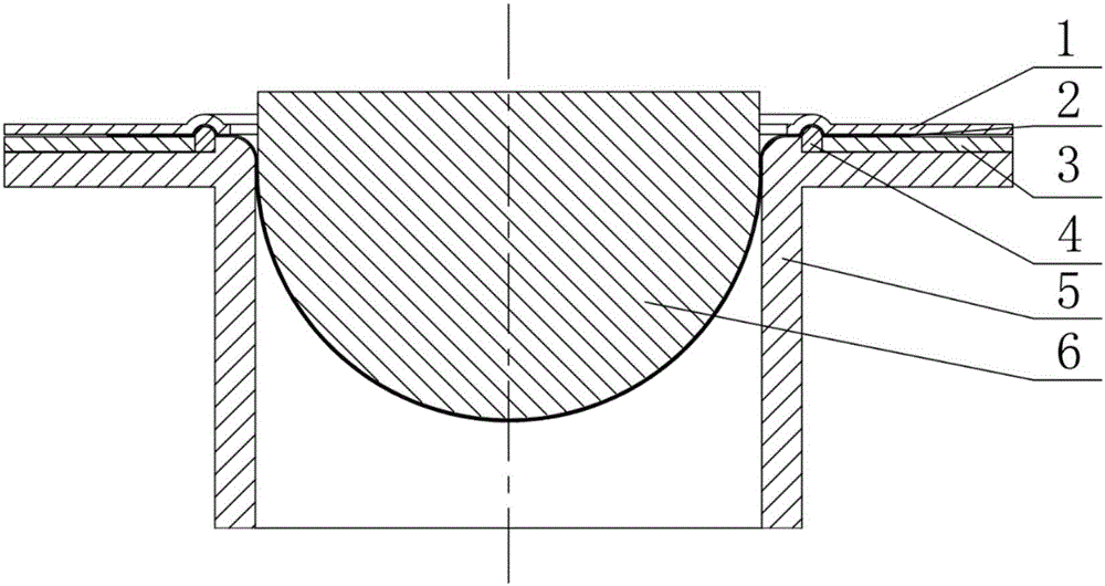
[0025] In this embodiment, a head forming mold with replaceable drawbeads adopts the modular design of detachable drawbeads and drawbead baffles, and is used in conjunction with a double-action press to realize the stamping and forming mold of the head. Multi-purpose. Specifically, if figure 1 , figure 2 , image 3 , Figure 4 As shown, the head forming mold includes: a binder plate 1, n drawbead baffles 3, n detachable drawbeads 4, a die 5, and a punch 6;

[0026] The punch 6 is installed on the inner slider of the double-action press, and the pressing plate 1 is installed on the outer slider of the double-action press;

[0027] There are n T-shaped grooves evenly distributed on the outer circumference of the die 5;

[0028] Any one of the drawbead baffles 3 and the detachable drawbead 4 is respectively provided with a T-shaped slider matched with the T-shaped groove;

[0029] n detachable drawbeads 4 are fixed on the outer circumference of the die 5 through n T-shaped...


PUM


Abstract

The invention discloses a sealing head forming mold with replaceable draw beads. The sealing head forming mold is matched with a double-action press and is characterized by comprising a pressing plate, n draw bead baffles, n detachable draw beads, a concave mold and a convex mold. Different draw bead baffles and detachable draw beads are replaced to form a mold for punching different draw beads. Through combination of different detachable draw beads and draw bead baffles, the replacement of the draw beads is achieved, so that different draw bead resistances are supplied for punching and forming sealing heads with different material thicknesses, and the purpose of punching the sealing heads with different material thicknesses by using the same mold can be achieved.

Description

technical field [0001] The invention belongs to the technical field of stamping dies, in particular to a head forming die with replaceable drawbeads, mainly for the head forming dies with replaceable drawbeads. Background technique [0002] As a pressure-bearing part, the head has different thickness requirements for heads with the same shape according to the specific pressure-bearing requirements. The early stamping forming was realized by the step-by-step forming of multiple molds. Although the step-by-step forming can realize the stamping and forming of the head, it has the disadvantages of cumbersome procedures, high production costs, and is not conducive to mass production; with the development of stamping technology, in The introduction of drawbeads in the head forming has realized the one-step cold stamping of the head, which is improved compared with the step-by-step forming, but there is still a single mold that can only produce one type of head, which has high prod...

Claims


Application Information

Patent Timeline
IPC IPC(8): B21D37/10B21D37/12
CPCB21D37/10B21D37/12
Inventor 赵坤民丁志杨陈梁玉吴寒陈还
Owner HEFEI UNIV OF TECH
Learn More