
Drilling tool on flow guide plate

A drilling tool and drainage plate technology, which is applied in the direction of manufacturing tools, boring/drilling, drilling/drilling equipment, etc., can solve the problems of drainage plate expansion, rupture, rainwater infiltration, etc.

Inactive Publication Date: 2016-11-16
STATE GRID CORP OF CHINA +2
View PDF14 Cites 0 Cited by
  • Summary
  • Abstract
  • Description
  • Claims
  • Application Information

AI Technical Summary

Problems solved by technology

[0002] The diversion plate is often used when the tension tower jumps and when the busbar in the substation introduces lightning arresters, voltage transformers and other equipment. For the latter, because the pressure interface of the diversion plate is upward, it is easy to cause rainwater to seep in during rainy and snowy weather.
Not only that, the long-term operation of the drainage plate will inevitably generate heat, and when the heat reaches a certain level, the rainwater in the crimping tube will be vaporized
Once the crimping interface is corroded and blocked, the drainage plate will expand due to thermal expansion and contraction, or even rupture, which will cause hidden dangers to the safe operation of the power grid, and the crimping interface will also appear hair suction

Method used


Image

  • Drilling tool on flow guide plate
  • Drilling tool on flow guide plate

Examples


Embodiment Construction

[0021] In order to make the purpose, technical solutions and advantages of the embodiments of the present invention clearer, the technical solutions in the embodiments of the present invention will be clearly and completely described below in conjunction with the drawings in the embodiments of the present invention. Obviously, the described embodiments It is a part of embodiments of the present invention, but not all embodiments. Based on the embodiments of the present invention, all other embodiments obtained by persons of ordinary skill in the art without making creative efforts belong to the protection scope of the present invention.

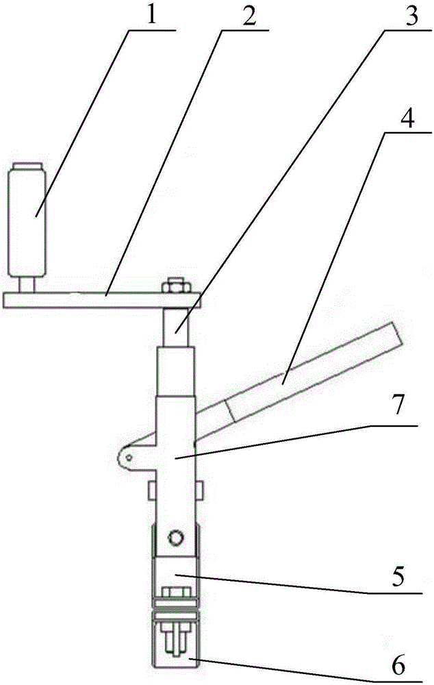
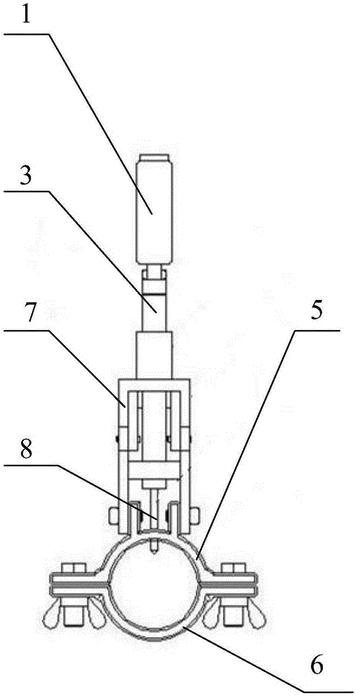
[0022] Please refer to figure 1 and figure 2 , figure 1 A schematic diagram of the front view structure of the drilling tool on the drainage plate provided by the embodiment of the present invention; figure 2 A schematic diagram of the side view structure of the drilling tool on the drainage plate provided by the embodiment of the presen...


PUM


Abstract

The invention discloses a drilling tool on a drain plate, which is used for live work, and comprises a fixing device, a bracket, a rotating device and a drill bit for fixing on the drain plate, wherein the bracket is fixed on the fixing device, The rotating device is rotatably arranged on the bracket, the drill bit is fixed at one end of the rotating device, and a through hole for the drill bit to pass is left on the fixing device. During use, the rotating device is fixed on the drainage plate by the fixing device, and then the rotating device rotates to drive the drill bit to drill the drainage plate to avoid hair suction.

Description

technical field [0001] The invention relates to the technical field of drilling, in particular to a drilling tool on a drainage plate. Background technique [0002] The diversion plate is often used when the tension tower jumps and when the busbar in the substation is introduced into lightning arresters, voltage transformers and other equipment. For the latter, because the pressure interface of the diversion plate is upward, it is easy to cause rainwater to seep in during rainy and snowy weather. Not only that, the long-term operation of the drainage plate will inevitably generate heat, and when the heat reaches a certain level, the rainwater in the crimping tube will vaporize. Once the crimping interface is corroded and blocked, the drainage plate will expand due to thermal expansion and contraction, or even rupture, which will cause hidden dangers to the safe operation of the power grid, and the crimping interface will also appear hair suction. [0003] Therefore, how to ...

Claims


Application Information

Patent Timeline
IPC IPC(8): B23B41/00B25H1/00
CPCB23B41/00B25H1/0078
Inventor 吴劲辉黄建峰孙福昌覃金彩钟素鹏王述汉罗绍青付军纪日升杨钊蒋卫东邹立勋吴坤祥郑琪傅寒凝刘红鑫汪丽波陈彩霞刘慧妍
Owner STATE GRID CORP OF CHINA
Features
  • Generate Ideas
  • Intellectual Property
  • Life Sciences
  • Materials
  • Tech Scout
  • Unparalleled Data Quality
  • Higher Quality Content
  • 60% Fewer Hallucinations
Learn More