Knife carriage drives for slitting machines

A tool holder driving and slitting machine technology, which is applied in the direction of shearing devices, knives used in shearing machine devices, shearing machine equipment, etc., can solve the problems of inconvenient tool holder replacement operations and inaccurate alignment, and achieve processing Low production cost, easy disassembly and simple structure

Active Publication Date: 2018-03-27
WUXI LEAD INTELLIGENT EQUIP CO LTD
View PDF9 Cites 0 Cited by
  • Summary
  • Abstract
  • Description
  • Claims
  • Application Information

AI Technical Summary

Problems solved by technology

Due to the misalignment between the spline shaft end and the floating spline sleeve, the replacement operation of the tool holder is not convenient enough

Method used


Image

  • Knife carriage drives for slitting machines
  • Knife carriage drives for slitting machines

Examples


Embodiment Construction

[0016] Embodiments of the invention are described in detail below, examples of which are illustrated in the accompanying drawings. The embodiments described below by referring to the figures are schematic and are intended to explain the present invention and not to limit the present invention.

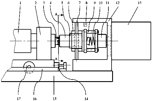
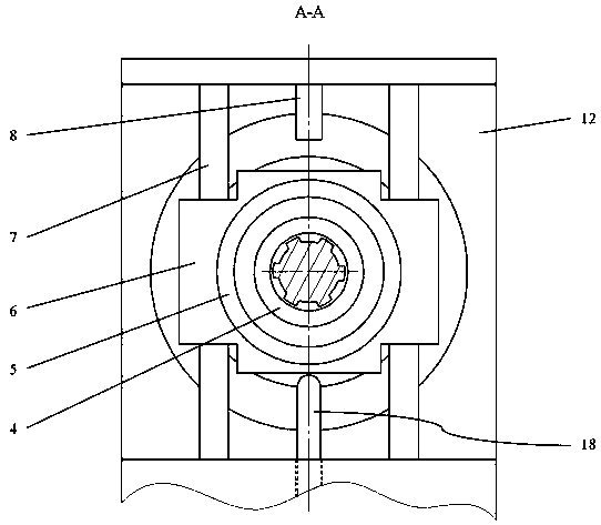
[0017] Refer below Figure 1-Figure 2 A knife rest driving device of a slitting machine according to an embodiment of the present invention is described.

[0018] A driving device for a slitting machine knife rest, comprising a base 15, a roller 17 is mounted on the knife shaft support 2 for rotation, the base 15 is provided with a groove for positioning the position of the knife shaft support 2 and cooperating with the roller 17, the knife shaft support 2 The two sides of the two sides are provided with the guide bar 16 that is used to guide the movement of the knife shaft support 2, and the guide bar 16 is fixed on the base 15, and the base 15 is also provided with a limit block 14 ...


PUM


Abstract

The invention discloses a tool rest drive device of a splitter. The tool rest drive device comprises a base, a tool shaft support arranged on the base in a sliding manner, a lower tool shaft rotationally borne on the tool shaft support, a spline shaft fixed to the shaft end of the lower tool shaft, a motor frame fixed to the base, and a servo motor fixed to the motor frame; a sliding base is in sliding connection to a sliding rod fixed to the motor frame, the base is in screw joint with a limiting screw used for abutting against the sliding base to prevent downward sliding of the sliding base, a sliding shaft sleeve is fixedly arranged in the sliding base, and the sliding shaft sleeve is internally provided with a spline sleeve in a clearance fit manner, and the spline sleeve is connected with the spline shaft; at least two drive rods are fixedly arranged at the flange end portion of the spline sleeve; and the drive rods are connected with grooves in a drive block fixed to the output shaft end of the servo motor. The tool rest drive device is simple in structure, connection of the lower tool shaft and a motor shaft can be rapidly finished by directly pushing and pulling a tool rest, the replacing operation of the tool rest is greatly facilitated, and the tool rest replacing time is saved.

Description

technical field [0001] The invention relates to a knife rest driving device, in particular to a knife rest driving device for a slitting machine. Background technique [0002] Existing slitting machines usually adopt a movable integral knife rest. The overall tool holder includes an upper cutter shaft and an upper blade installed thereon, a lower cutter shaft and a lower blade installed thereon. The driving end of the knife post generally adopts a spline structure, and the upper and lower knife shafts of the knife post are driven to rotate through the docking of the spline shaft end with the floating spline sleeve on the slitting machine. Since the misalignment is prone to occur between the spline shaft end and the floating spline sleeve, the replacement operation of the tool holder is not convenient enough. Contents of the invention [0003] The purpose of the present invention is to overcome the deficiencies in the prior art and provide a tool holder driving device for...

Claims


Application Information

Patent Timeline
Patent Type & Authority Patents(China)
IPC IPC(8): B23D15/12B23D35/00
CPCB23D15/12B23D35/002
Inventor 涂新平朱千良
Owner WUXI LEAD INTELLIGENT EQUIP CO LTD
Why Eureka
Try Eureka