Front lower sway arm assembly

A front lower swing arm and assembly technology, which is applied to the cantilever mounted on the pivot, suspension, transportation and packaging, etc., can solve the problems of short service life, poor versatility, and large impact force of the rear bushing

Active Publication Date: 2016-11-16
NINGBO YONGXIN AUTO COMPONENTS MFG
View PDF6 Cites 1 Cited by
  • Summary
  • Abstract
  • Description
  • Claims
  • Application Information

AI Technical Summary

Problems solved by technology

[0002] The suspension of a car is an assembly that connects all transmission and connection devices between the car body and the wheels. Its main function is to transmit all forces and moments acting between the wheels and the body, and to slow down the vibration transmitted from the wheels to the body during driving. , to improve the stability and comfort of driving. The suspension includes front suspension and rear suspension. The longitudinal force and lateral force during braking and turning are one of the key components that determine the performance of the vehicle. The lower arm assembly of the front suspension is mainly connected with the front sub-frame assembly through the front bush and the rear bush The ball joint of the swing arm is connected with the steering knuckle and the steering guide mechanism. According to the existing technology, the front lower swing arm assembly of the automobile is made of nodular cast iron, which is heavy, high in cost, and poor in versatility. At the same time, there is no avoidance structure, resulting in It cannot be used for other models, and cannot meet more than two models at the same time. The versatility is poor. If other materials are used to produce the front lower arm assembly of the automobile, according to the current structure, it cannot meet the load-carrying capacity requirements after the material is changed and cannot avoid transmission mechanisms such as drive shafts. , at the same time, the rear bush is connected with the frame, the friction between the rear bush and the frame will generate noise, the impact force on the rear bush is large, the rear bush is easily damaged, and the service life is short

Method used


Image

  • Front lower sway arm assembly
  • Front lower sway arm assembly
  • Front lower sway arm assembly

Examples


Embodiment Construction

[0023] The present invention will be further described below in conjunction with the accompanying drawings and specific embodiments.

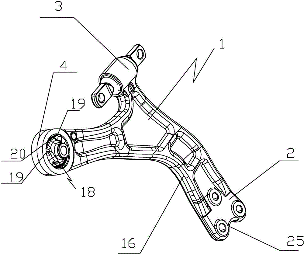
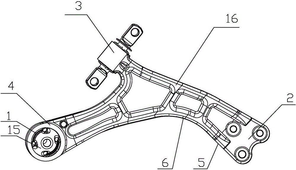
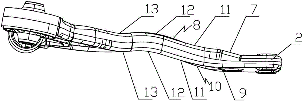
[0024]As shown in the figure, the present invention provides a front lower swing arm assembly, which includes a lower swing arm main body assembly 1, and the lower swing arm main body assembly 1 is provided with a ball joint assembly 2, a front bush 3 and a rear bush 4. There is a swing arm 16 between the ball head assembly 2 and the front bush 3, and the rear bush 4 is provided with an outer sleeve 14 and an inner sleeve 15 inside the outer sleeve 14, so An annular rubber body 17 is provided between the outer sleeve 14 and the inner sleeve 15, and a pair of limiting holes 18 are provided on the annular rubber body 17, and the limiting holes 18 are symmetrical about the center of the inner sleeve 15. , the limiting hole 18 includes two through holes 19 and a damping hole 20, the damping hole 20 communicates with the two through holes 19, the ma...


PUM


Abstract

The invention discloses a front lower sway arm assembly which comprises a lower sway arm body assembly (1). The lower sway arm body assembly (1) is provided with a ball head assembly (2), a front bushing (3) and a rear bushing (4), a sway arm (16) is arranged between the ball head assembly (2) and the front bushing (3), the rear bushing (4) is internally provided with an outer sleeve (14) and an inner sleeve (15) arranged in the outer sleeve (14), an annular rubber body (17) is arranged between the outer sleeve (14) and the inner sleeve (15), and the annular rubber body (17) is provided with a pair of limiting holes (18) which are symmetrical about the center of the inner sleeve (15). According to the front lower sway arm assembly, the requirement on the bearing capacity after the material is changed can be met, transmission mechanisms of a transmission shaft and the like can be avoided, the weight is the lightest, the cost is low, the universality is good, noise cannot be generated by friction between the rear bushing and a frame, and the service life of the rear bushing is long.

Description

technical field [0001] The invention relates to the field of auto parts, in particular to a front lower swing arm assembly. Background technique [0002] The suspension of a car is an assembly that connects all transmission and connection devices between the car body and the wheels. Its main function is to transmit all forces and moments acting between the wheels and the body, and to slow down the vibration transmitted from the wheels to the body during driving. , to improve the stability and comfort of driving. The suspension includes front suspension and rear suspension. The longitudinal force and lateral force during braking and turning are one of the key components that determine the performance of the vehicle. The lower arm assembly of the front suspension is mainly connected with the front sub-frame assembly through the front bush and the rear bush The ball joint of the swing arm is connected with the steering knuckle and the steering guide mechanism. According to the...

Claims


Application Information

Patent Timeline
Patent Type & Authority Applications(China)
IPC IPC(8): B60G7/00
CPCB60G7/00B60G2206/7102B60G2206/81022
Inventor 柴明军王泉胜胡高强叶浩梁
Owner NINGBO YONGXIN AUTO COMPONENTS MFG
Why Eureka
Try Eureka