Novel speed reduction clutch of intelligent washing machine

A deceleration clutch and washing machine technology, applied in the field of clutches, can solve the problems of not being able to normally apply large-capacity clutches for washing and dehydration, affecting the service life of clutch devices and washing machines, and being unable to apply to large-capacity washing machines, etc., to achieve simple structure and long service life , the effect of easy installation

Inactive Publication Date: 2016-11-16
ZHEJIANG SANXING MECHANICAL & ELECTRONICSAL STOCK
View PDF6 Cites 0 Cited by
  • Summary
  • Abstract
  • Description
  • Claims
  • Application Information

AI Technical Summary

Problems solved by technology

With the increasing demand for large-capacity washing machines, the clutch device with a square wire spring clutch has a short service life, poor durability, and unreliable clutch work, and it cannot be applied to large-capacity washing machines.
This traditional clutch is only suitable for general-capacity washing machines, and it is not suitable for large-capacity clutches to perform washing and dehydration work under the high-speed operation of the input shaft.
If after a long time of washing and dehydration, the square wire spring is likely to break due to the excessive starting torque of the clutch, the limit distance of the brake arm is widened, and the displacement of the pawl is too small, etc., which will cause the clutch to fail. Poor durability, which affects the life of the clutch and washing machine

Method used


Image

  • Novel speed reduction clutch of intelligent washing machine
  • Novel speed reduction clutch of intelligent washing machine
  • Novel speed reduction clutch of intelligent washing machine

Examples


Embodiment Construction

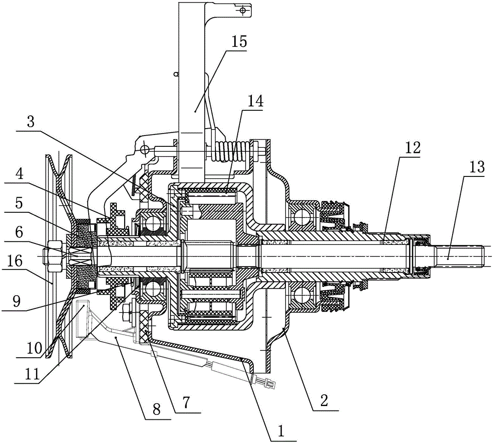
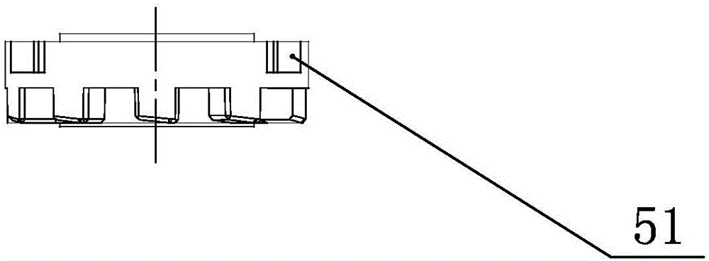
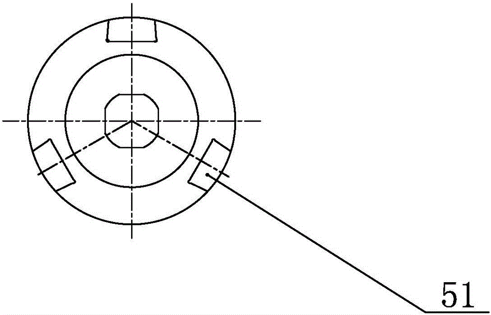
[0016] see figure 1 , figure 2 and image 3 , a new deceleration clutch for an intelligent washing machine disclosed in the present invention, comprising a lower housing 1, an upper housing 2, a brake wheel cover 3, a connecting disc 4, and a torque transmission sleeve 5, and the lower housing 1 is set with a system The driving wheel cover 3 and the brake wheel cover 3 are provided with an input shaft 6, the brake wheel cover 3 and the input shaft 6 are coaxially arranged, the torque transmission sleeve 5 is sleeved on the input shaft 6, and the torque transmission shaft A groove 51 is provided on the outer wall of the sleeve 5, and a magnet is embedded in the groove 51, and the magnet is connected and installed in the groove 51 by magnetic force, and a positioning disc 7 is arranged on the lower side of the lower housing, so that The positioning plate 7 is provided with a Hall sensor mounting frame 8, the lower end surface of the positioning plate 7 is connected with the l...


PUM


Abstract

The invention discloses a novel speed reduction clutch of an intelligent washing machine. The novel speed reduction clutch comprises a lower shell, an upper shell, a brake wheel cap, a connecting disc and a torque transmission shaft sleeve; an input shaft is sleeved with the brake wheel cap, the brake wheel cap and the input shaft are coaxially arranged, the torque transmission shaft sleeve is installed on the input shaft in a sleeving mode, grooves are formed in the outer wall of the torque transmission shaft sleeve, and magnets are embedded in the grooves; a positioning disc is arranged at the lower end of the lower shell, a Hall sensor installing frame is installed on the positioning disc, the lower end face of the positioning disc is connected with the lower shell, the upper end face of the positioning disc is connected with the Hall sensor installing frame, the Hall sensor installing frame and the positioning disc are fastened to the lower shell through bolts, a Hall sensor is arranged in one end of the Hall sensor installing frame, the installing position of the Hall sensor is matched with the magnets, and the magnets and the Hall sensor are located on the same radial face. By means of the technical scheme, the novel speed reduction clutch is reasonable in structural design, simple in structure, convenient to assemble, safe and reliable in clutch motion, good in washing and dewatering effect and long in service life.

Description

technical field [0001] The invention relates to the technical field of clutches for washing machines, in particular to a deceleration clutch for a novel intelligent washing machine. Background technique [0002] At present, the traditional deceleration clutch of washing machine is provided with structures such as a clutch device, a brake device, and a speed reducer device. But most clutches on the market, the clutch device that adopts is generally square wire spring, ratchet, ratchet, brake arm, push arm etc. With the increasing demand for large-capacity washing machines, the clutch device with a square wire spring clutch has a short service life, poor durability, and unreliable clutch work, and it cannot be applied to large-capacity washing machines. . This traditional clutch is only applicable to the washing machine of general capacity, and it itself has been unable to normally be suitable for large-capacity clutch to carry out washing and dehydration work under the high...

Claims


Application Information

Patent Timeline
Patent Type & Authority Applications(China)
IPC IPC(8): D06F37/30
CPCD06F37/30
Inventor 缪立春任强军应元钞林华斌许益勇叶克雷许鹏陈荣誉许道岳陈康康
Owner ZHEJIANG SANXING MECHANICAL & ELECTRONICSAL STOCK
Why Eureka
Try Eureka