
Double-tube constraining fabricated type anti-buckling supporting member

An anti-buckling bracing and prefabricated technology, applied in building components, earthquake-proof, protective buildings/shelters, etc., can solve the problems of long production time, difficult production limit, difficult adjustment, etc., and achieve simple and easy access to components. , Strong operability, reducing the effect of welding parts

Inactive Publication Date: 2016-11-16
石飞停
View PDF0 Cites 5 Cited by
  • Summary
  • Abstract
  • Description
  • Claims
  • Application Information

AI Technical Summary

Problems solved by technology

The use of this type of support has the following problems: (1) For components filled with concrete or mortar, it takes a long time to manufacture; (2) The gap treatment of the constrained non-yielding section is more complicated, the manufacturing limit is more difficult, and the manufacturing monitoring is difficult; (3) There is no It is difficult to control the bonding layer gap, and the unbonded material consumes a lot; (4) When the component is damaged, the external constraints cannot be reused, which greatly wastes materials; (5) When applied to structures, if the structure is subjected to force, it cannot Timely and effective observation of whether components need to be replaced; (6) The stiffness and restraint performance of external constraints are not easy to adjust after the components are fabricated. Although some components can replace the core unit at present, they are greatly restricted

Method used


Image

  • Double-tube constraining fabricated type anti-buckling supporting member
  • Double-tube constraining fabricated type anti-buckling supporting member
  • Double-tube constraining fabricated type anti-buckling supporting member

Examples


Embodiment Construction

[0031] The accompanying drawings disclose non-restrictive structural schematic diagrams of preferred embodiments involved in the present invention, and the present invention will be further described below in conjunction with the accompanying drawings and embodiments.

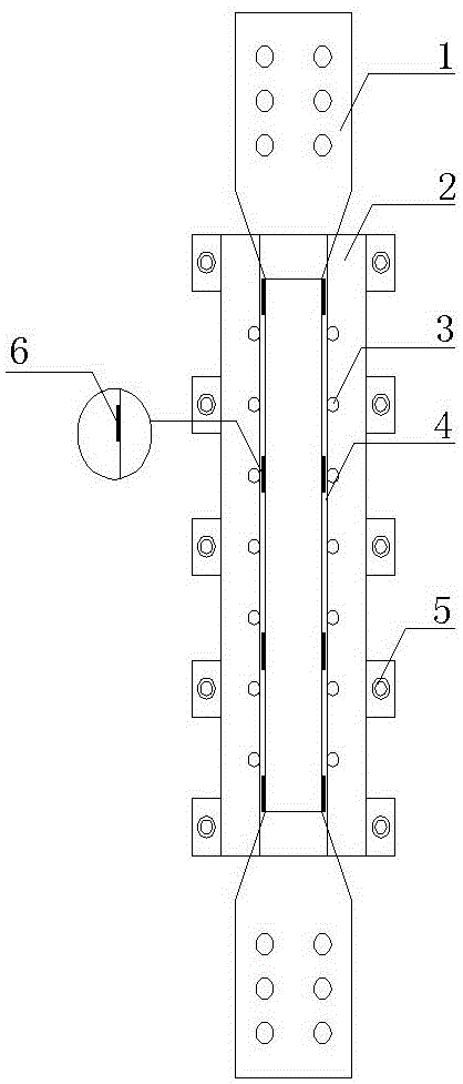
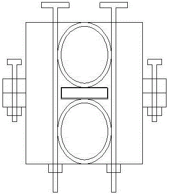
[0032] Such as figure 1 , figure 2 For the front view and top view of the buckling-resistant bracing member with double-tube restraint assembly, first determine the size of the core element required for the selection design, and determine (4) the type and size of the core element. Determined by the size type of the core unit (4) the size of the double steel pipe unit and (3) the number of restraint bolts, according to the size of (4) the size of the double steel pipe unit and (3) the number of restraint bolts Disassemble the size of the square steel pipe groove opening and the number of connecting bolts.

[0033] The double-tube constrained assembled anti-buckling support member includes an outer restraint u...


PUM

PropertyMeasurementUnit
Widthaaaaaaaaaa
Thicknessaaaaaaaaaa

Abstract

The invention discloses a double-tube constraining fabricated type anti-buckling supporting member. The double-tube constraining fabricated type anti-buckling supporting member comprises peripheral detachable square steel tube grooves, a double-steel-tube unit, and constraining bolts. The main function of the peripheral detachable square steel tube grooves is to improve peripheral constraining stiffness and to provide the double-steel-tube unit with a position limiting function; the double-steel-tube unit is mainly used for constraining a core unit to prevent the core unit from buckling by compression; the constraining bolts are mainly used for squeezing and limiting the core unit and the double-steel-tube unit to constrain the double-steel-tube unit from sliding. Meanwhile the double-barreled constraining fabricating type anti-buckling supporting member further comprises the core unit, connecting bolts and part of unbounded materials. Compared with a traditional anti-buckling supporting member, the double-tube constraining fabricated type anti-buckling supporting member has the obvious advantages that the manufacture is simple; the installation is convenient; a gap between the core unit and the constraining unit is easy to control and scale; meanwhile, when the core unit is destroyed, the core unit can be replaced; and the peripheral constraining unit and other parts can be reused and are economical and convenient.

Description

technical field [0001] The invention relates to an anti-seismic energy-consuming part of an engineering structure, in particular to a double-tube constrained assembled anti-buckling support member which is externally constrained and reusable, and which is simple and convenient to install and limit, and has certain engineering application prospects. , belonging to the technical field of structural engineering. Background technique [0002] The anti-buckling support is mainly composed of three parts: external constraints, core elements and unbonded material (gap). The components are subjected to axial loads by the core elements, and the external constraints mainly provide the constraints of the core elements to prevent the core elements from being destabilized under pressure. This allows the member to yield under both tension and compression. The unbonded material (gap) avoids the contact between the core element and the external constraint, so that the external constraint el...

Claims


Application Information

Patent Timeline
IPC IPC(8): E04B1/98E04H9/02
CPCE04H9/021
Inventor 石飞停甘亚南徐兵
Owner 石飞停
Learn More