
Detachable anti-buckling supporting member constrained by bolts

An anti-buckling bracing and bolt technology, applied in building components, anti-vibration and other directions, can solve the problems of difficulty in manufacturing limit, waste of materials, and high consumption of unbonded materials, so as to avoid overall or local instability, improve restraint performance, Actionable performance

Active Publication Date: 2015-06-24
HOHAI UNIV
View PDF8 Cites 2 Cited by
  • Summary
  • Abstract
  • Description
  • Claims
  • Application Information

AI Technical Summary

Problems solved by technology

The use of this type of support has the following problems: (1) When the component is damaged, the external constraints cannot be reused, which greatly wastes materials; (2) The gap processing of the non-yielding section of the constraints is more complicated, the production limit is more difficult, and the production monitoring is difficult ; (3) It is difficult to control the gap of the unbonded layer, and the consumption of unbonded materials is large; (4) When it is applied to the structure, if the structure is under the action of force, it cannot be timely and effectively observed whether the components need to be replaced; (5) For filled concrete or mortar components, the production time is long
(6) The stiffness and restraint performance of external constraints are not easy to adjust after the components are fabricated. Although some components can replace the core unit at present, they are greatly restricted

Method used


Image

  • Detachable anti-buckling supporting member constrained by bolts
  • Detachable anti-buckling supporting member constrained by bolts
  • Detachable anti-buckling supporting member constrained by bolts

Examples


Embodiment Construction

[0037] The accompanying drawings disclose non-restrictive structural schematic diagrams of preferred embodiments involved in the present invention, and the present invention will be further described below in conjunction with the accompanying drawings and embodiments.

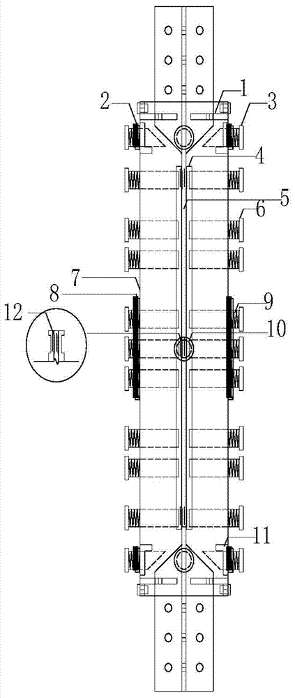
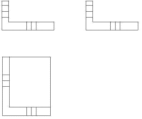
[0038] like figure 1 , figure 2 For the schematic diagram of bolt-constrained detachable buckling-resistant braces, first determine the core elements required by the design, and determine (5) the type and size of the core elements. Determined by the size and type of the core unit (6) The number and size of bolts, determined by the length of the core unit and the number of bolt sizes (7) The size of the square steel pipe, design the positioning constraint bolt holes and limit bolt holes on the peripheral square steel pipe .

[0039] The detachable anti-buckling support member constrained by bolts includes an outer restraint unit and a core unit. The core unit is wrapped with a layer of 1cm-wide non-adhesive s...


PUM

PropertyMeasurementUnit
Widthaaaaaaaaaa
Thicknessaaaaaaaaaa

Abstract

The invention discloses a detachable anti-buckling supporting member constrained by bolts. The detachable anti-buckling supporting member constrained by the bolts comprises a peripheral bolt positioning square steel tube, the bolts, a transition clamp plate, springs, reinforced ribbed plates and partial unbonded material layers. The main function of the peripheral bolt positioning square steel tube is to provide positioning for the bolts and support limiting for a core unit. The bolts are mainly used for constraining the core unit, so that the core unit is prevented from being buckled due to compression. The transition clamp plate is used for improving the constraining performance of the bolts. The detachable anti-buckling supporting member constrained by the bolts is obviously different from a traditional anti-buckling supporting member, the manufacturing complex degree is lowered, installing and positioning are easy by using the bolts to carry out constraining, the core unit is easy to center, a gap between the core unit and the constraint is very easy to control, back-and-forth deploying and retracting can be achieved, the manufacturing process of the member is easy to control, meanwhile, only the core unit needs to be replaced, the outer constraint can be reused, and the whole member is economical and convenient.

Description

technical field [0001] The invention relates to an anti-seismic energy-consuming part of an engineering structure, in particular to a buckling-resistant support member which is externally constrained and reusable, and which is simple and convenient to install and limit and has engineering application prospects. It belongs to the structure field of engineering technology. Background technique [0002] The anti-buckling support is mainly composed of three parts: external constraints, core elements and unbonded material (gap). The components are subjected to axial loads by the core elements, and the external constraints mainly provide constraints for the core elements to prevent the core elements from being destabilized under pressure. This allows the member to yield under both tension and compression. The non-bonding material (gap) avoids the contact between the core element and the external constraint, so that the external constraint element does not participate in the axial...

Claims


Application Information

Patent Timeline
IPC IPC(8): E04B1/98
Inventor 傅中秋吉伯海余振鹏许国杰
Owner HOHAI UNIV
Learn More