Encoder system and method of assembling an encoder system

a technology of encoder system and encoder, which is applied in the field of encoder system, can solve the problems of high cost of encoder system and high cost of prior art production method, and achieve the effect of high degree of accuracy

Inactive Publication Date: 2005-11-01
PWB RUHLATEC INDPROD
View PDF32 Cites 10 Cited by
  • Summary
  • Abstract
  • Description
  • Claims
  • Application Information

AI Technical Summary

Benefits of technology

[0006]It is therefore the object of the present invention to develop an encoder system as well as a method of assembling an encoder system, wherein the processes of centering the timing disc on the motor shaft and positioning the sensor-emitter unit can be performed in one operating step, and wherein the tools and assembly devices can be controlled in the simplest possible way and therefore with a high degree of accuracy.SUMMARY OF THE INVENTION
[0017]It is advantageous, prior to sliding the circuit board on the centering collar, to apply an adhesive to the recess of the circuit board and to allow the adhesive bond to harden after the inserting and rotating steps.
[0018]It has been found that as a result of the inventive design of the new encoder system, easy centering of the timing disc and of the circuit board can be achieved with only two feed advance movements of the assembly system. The two movements can be carried out independently of one another, so that there is no need to move into any intermediate positions. Installation can take place with largely preassembled elements in a single operation, thus achieving large production runs of 1000 parts per hour on one production unit.

Problems solved by technology

In an automated assembly process of the encoder system, the problem presents itself that feed advance movements have to be carried out along several axes, where the need for a high degree of precision imposes special requirements on assembly devices, feed advance movements, and guide elements for the moving parts of the assembly machine.
Encoder systems are therefore expensive, and the prior art production methods are failure prone.

Method used


Image

  • Encoder system and method of assembling an encoder system
  • Encoder system and method of assembling an encoder system
  • Encoder system and method of assembling an encoder system

Examples


Embodiment Construction

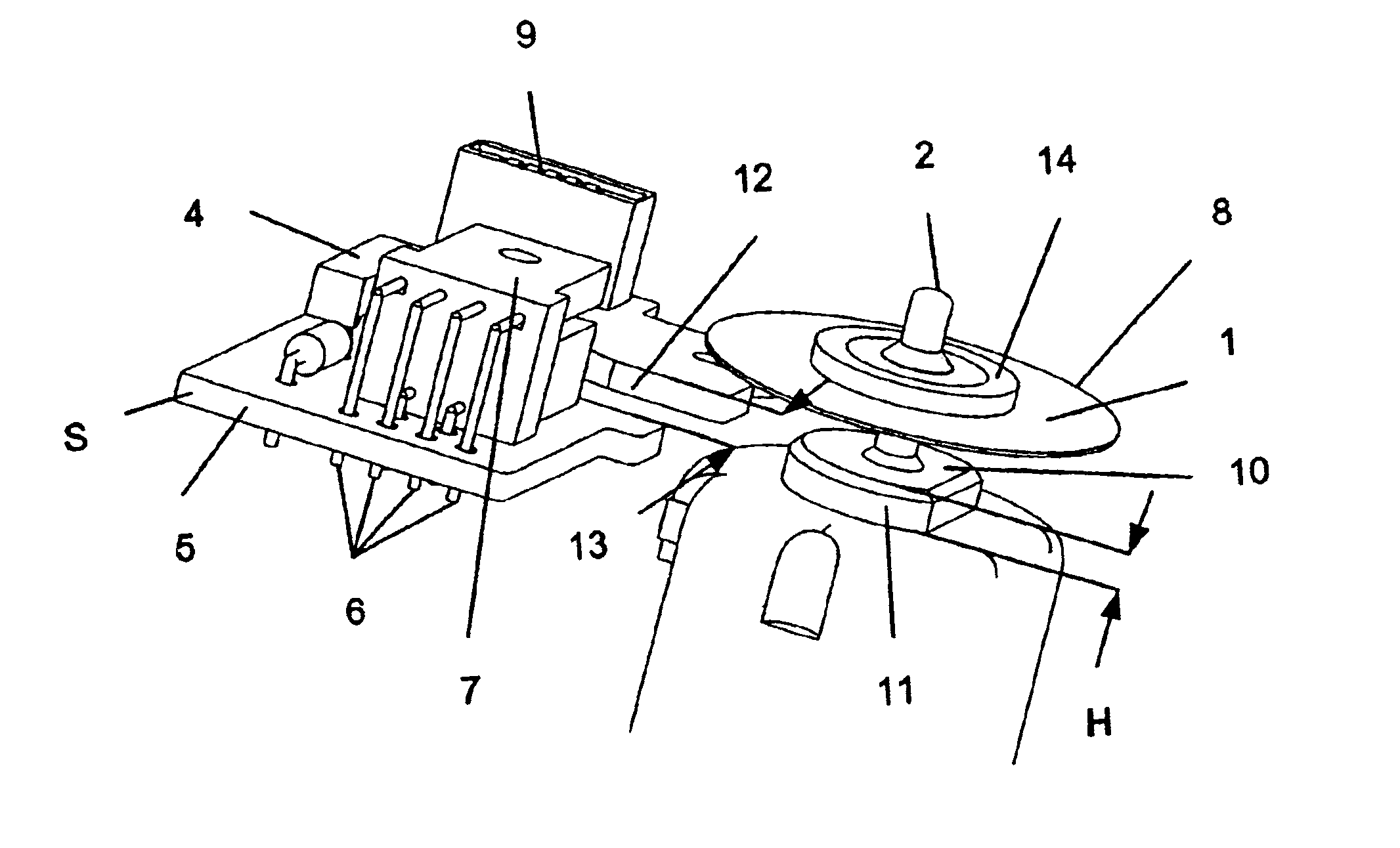
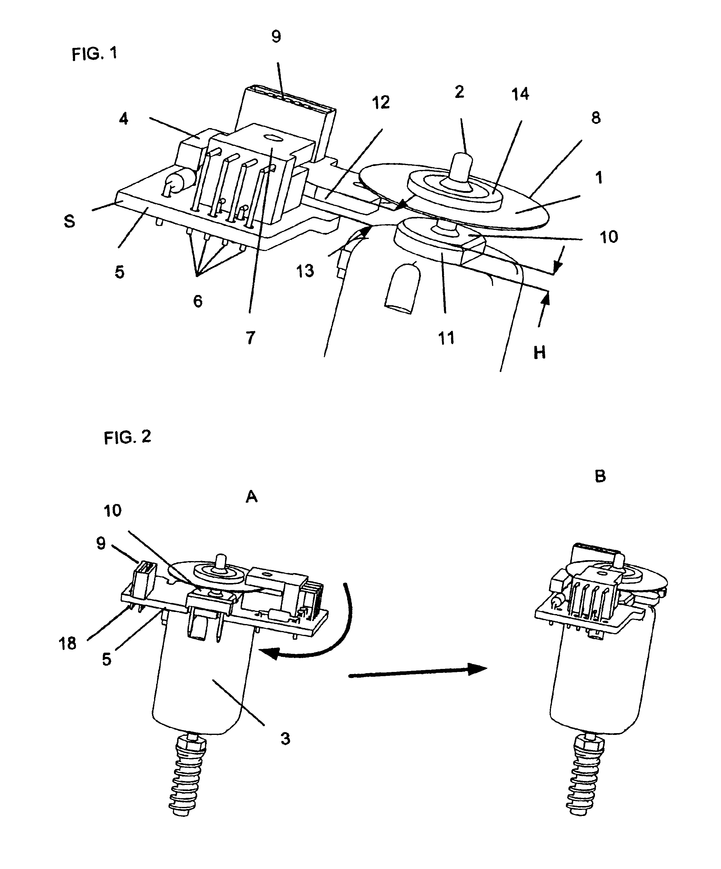
[0024]FIG. 1 shows an encoder system according to the invention. The timing disc 1 has a timing disc hub 14 for centering purposes and is designed so that it can be mounted on a motor shaft 2. The circuit board 5 has a sensor-emitter unit 7 and a plug-in connector 9.

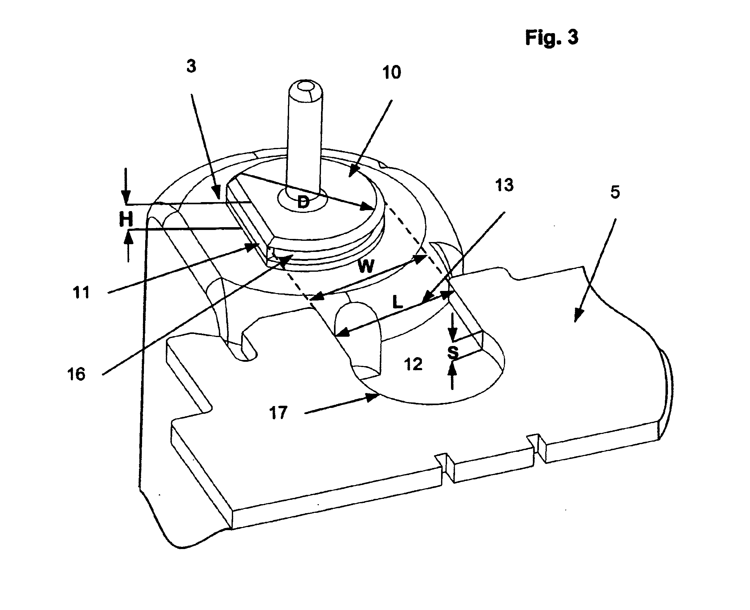
[0025]The motor shaft 2 forms part of an electric motor 3. At the upward end of the motor 3, in the flange plane where the motor shaft 2 protrudes through an opening, the motor flange has a centering collar 10 with a flattened portion 11. The shape of the centering collar 10 is designed to permit centering of the motor 3 in the flange plane with reference to the sensor-emitter unit 7 and the timing disc 1. The circuit board 5 has an opening 13 so that the circuit board can be slid over the centering collar into a position where the centering collar is seated in a correspondingly shaped recess 12.

[0026]The circuit board 5 carries all the connections required for the supply of power to the connecting leads 6 of the sensor-...


PUM

PropertyMeasurementUnit
angleaaaaaaaaaa
rotationaaaaaaaaaa
mechanicalaaaaaaaaaa

Abstract

An encoder system with a timing disc includes a preassembled circuit board with a U-shaped sensor / emitter embracing the edge of the timing disc. The timing disc is configured to be slipped onto a motor shaft at the flange end of an electric motor, and the circuit board is designed to be mounted on the flange of the motor by mechanical, thermal, and / or adhesive means of attachment. The motor flange is equipped with a centering collar that has a flattened portion on its otherwise circular circumference. The circuit board has a cutout opening that receives the centering collar in a form-fitting way when the circuit board is slid onto the flange of the motor. By rotating the circuit board 90° about the centering collar, the circuit board is secured in a defined position on the motor flange.

Description

BACKGROUND OF THE INVENTION[0001]The invention relates to an encoder system with a plurality of elements forming an assembly that can be fastened to the flange end of an electric motor by mechanical, thermal, and / or adhesive means of attachment. The encoder system includes a timing disc, a circuit board, and a plug-in connector. The timing disc can be slipped onto a motor shaft at the flange end of an electric motor. The motor can be connected to a power source by means of contact elements. The circuit board has connections for a U-shaped sensor-emitter unit which embraces the edge of the timing disc and is adjustable in all three spatial directions to permit the reception of position signals. The plug-in connector has connecting leads forming electrically conductive connections between the elements forming the assembly.[0002]The invention further relates to a method of installing an encoder system of a design that meets the foregoing description.[0003]Encoder systems of the type de...

Claims


Application Information

Patent Timeline
Patent Type & Authority Patents(United States)
IPC IPC(8): H02K11/00G01D11/24G01D5/245H02K29/00H05K1/18
CPCG01D11/245H02K11/0015H02K11/0068Y10T29/49004H05K1/182H02K11/21H02K11/30
Inventor TENCA, VITTORIOCARRADORI, CORRADO
Owner PWB RUHLATEC INDPROD
Why Eureka
Try Eureka